3.6 Main Circuit Wiring
This section describes the functions, specifications, and procedures required to safely and properly wire the main circuit
of the drive.
NOTICE: Do not solder the ends of wire connections to the drive. Soldered wiring connections can loosen over time. Improper wiring
practices could result in drive malfunction due to loose terminal connections.
u
Main Circuit Terminal Functions
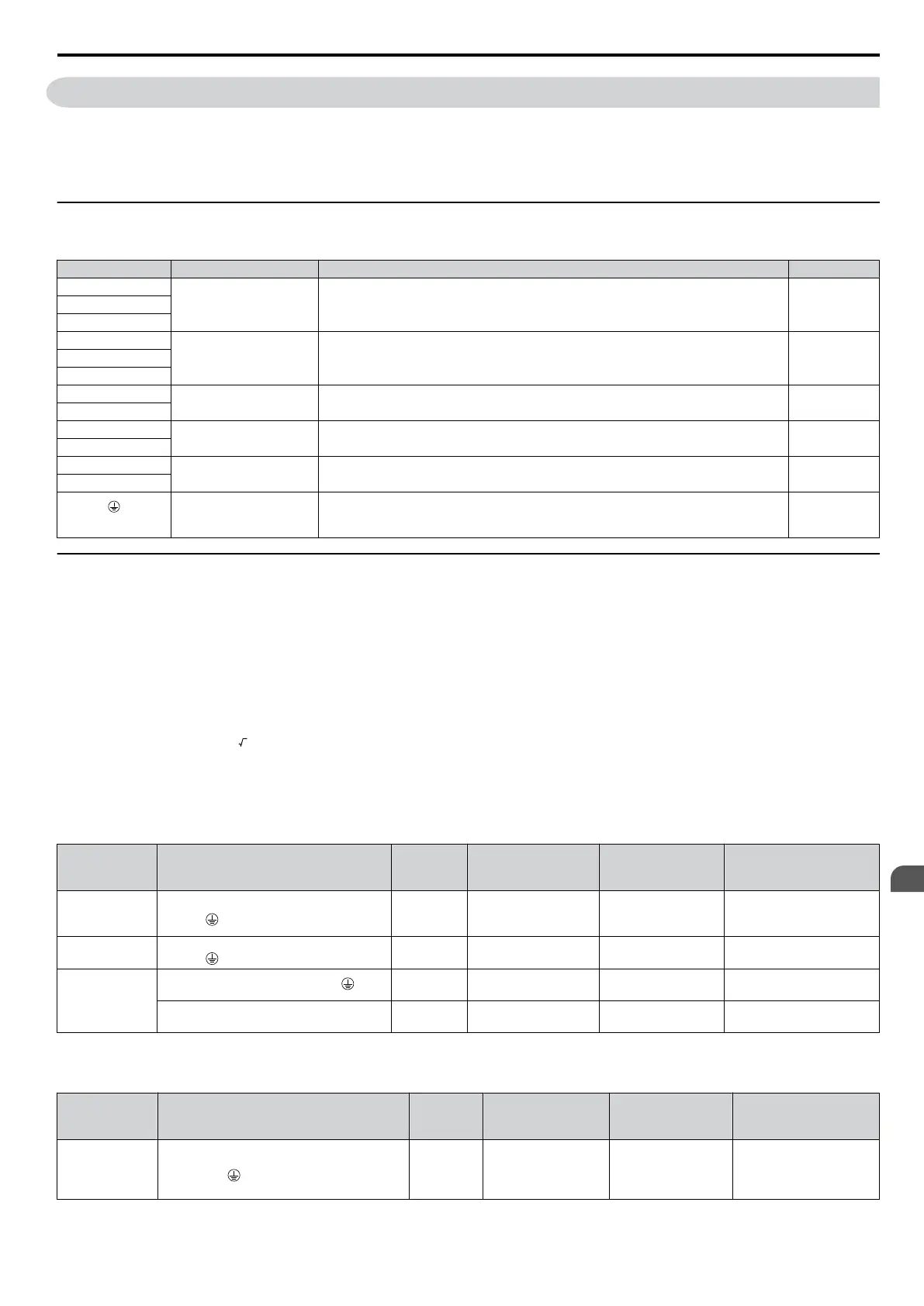
Table 3.1 Main Circuit Terminal Functions
Terminal Type Function Reference
R/L1
Main circuit power
supply input
Connects line power to the drive.
Drives with single-phase 200 V input power use terminals R/L1 and S/L2 only (T/
L3 must not be used).
34S/L2
T/L3
U/T1
Drive output Connects to the motor. 38V/T2
W/T3
B1
Braking resistor Available for connecting a braking resistor or the braking resistor unit option. 47
B2
+1
DC reactor connection
These terminals are shorted at shipment. Remove the shorting bar between +1 and
+2 when connecting a DC reactor to this terminal.
153
+2
+1
DC power supply input For connecting a DC power supply. –
–
(2 terminals)
Ground
Grounding Terminal
For 200 V class: 100 Ω or less
For 400 V class: 10 Ω or less
38
u
Wire Gauges and Tightening Torque
Select the appropriate wires and crimp terminals from Table 3.2 through Table 3.4.
Note: 1. Wire gauge recommendations based on drive continuous current ratings using 75
°C 600 Vac vinyl-sheathed wire assuming ambient
temperature within 30 °C and wiring distance less than 100 m.
2. Terminals +1, +2, –, B1 and B2 are for connecting optional devices such as a DC reactor or braking resistor. Do not connect other
non-specified devices to these terminals.
• Consider the amount of voltage drop when selecting wire gauges. Increase the wire gauge when the voltage drop is
greater than 2% of motor rated voltage. Ensure the wire gauge is suitable for the terminal block. Use the following
formula to calculate the amount of voltage drop:
•
Line drop voltage (V) =
3 x wire resistance (Ω/km) x wire length (m) x current (A) x 10
-3
•
Refer to instruction manual TOBPC72060000 for braking unit or braking resistor unit wire gauges.
• Refer to UL Standards Compliance on page 218 for information on UL compliance.
n
Single-Phase 200 V Class
Table 3.2 Wire Gauge and Torque Specifications
Model
JZA
Terminal Screw Size
Tightening
Torque
N•m (lb.in.)
Applicable
Gauge
mm
2
(AWG)
Recommended
Gauge
mm
2
(AWG)
B0P1
B0P2
B0P4
R/L1, S/L2, U/T1, V/T2, W/T3, –, +1, +2,
B1, B2,
M3.5
0.8 to 1.0
(7.1 to 8.9)
0.75 to 2.5
(18 to 14)
2.5
(14)
B0P7
R/L1, S/L2, U/T1, V/T2, W/T3, –, +1, +2,
B1, B2,
M4
1.2 to 1.5
(10.6 to 13.3)
2.5 to 6
(14 to 10)
2.5
(14)
B1P5
R/L1, S/L2, U/T1, V/T2, W/T3,
M4
1.2 to 1.5
(10.6 to 13.3)
2.5 to 6.0
(14 to 10)
4
(12)
–, +1, +2, B1, B2 M4
1.2 to 1.5
(10.6 to 13.3)
2.5 to 6.0
(14 to 10)
6
(10)
n
Three-Phase 200 V Class
Table 3.3 Wire Gauge and Torque Specifications
Model
JZA
Terminal
Screw
Size
Tightening
Torque
N•m (lb.in.)
Applicable
Gauge
mm
2
(AWG)
Recommended
Gauge
mm
2
(AWG)
20P1
20P2
20P4
20P7
R/L1, S/L2, T/L3, U/T1, V/T2, W/T3, –, +1,
+2, B1, B2,
M3.5
0.8 to 1.0
(7.1 to 8.9)
0.75 to 2.5
(18 to 14)
2.5
(14)
3.6 Main Circuit Wiring
SIEP C710606 33A OYMC AC Drive – J1000 User Manual
37
3
Electrical Installation
 Loading...


