6.3 Drive Alarms, Faults, and Errors
u
Types of Alarms, Faults, and Errors
Check the LED operator for information about possible faults if the drive or motor fails to operate. Refer to Using the
Digital LED Operator on page 54.
If problems occur that are not covered in this manual, contact the nearest OYMC representative with the following
information:
•
Drive model
• Software version
• Date of purchase
• Description of the problem
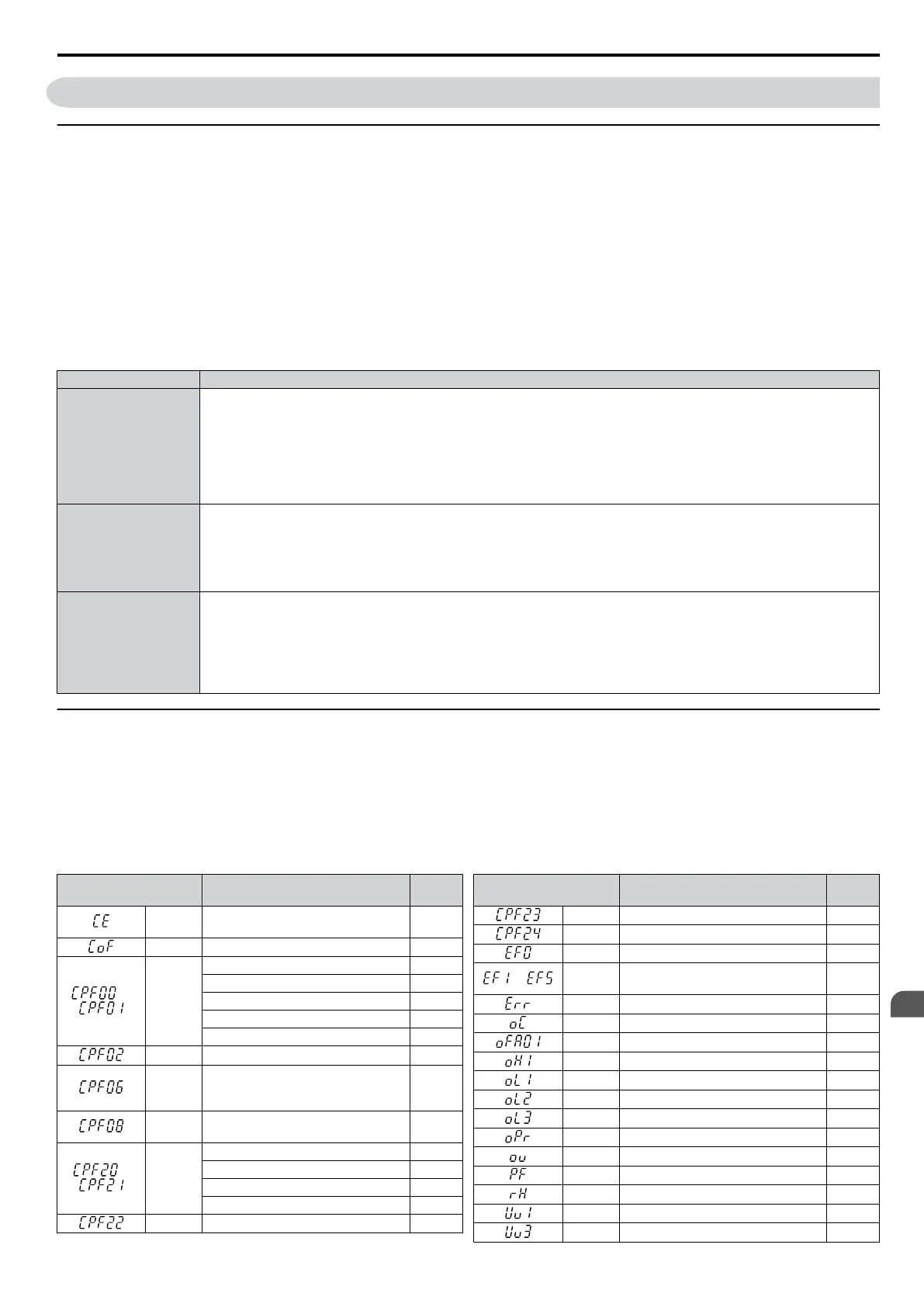
Table 6.3 contains descriptions of the various types of alarms, faults, and errors that may occur while operating the drive.
Table 6.3 Types of Alarms, Faults, and Errors
Type Drive Responses to Alarms, Faults, and Errors
Faults
When the drive detects a fault:
• The digital operator displays text that indicates the specific fault and the ALM indicator LED remains lit until the fault
is reset.
• The fault interrupts drive output and the motor coasts to a stop.
• Depending on the setting, the drive and motor may stop via different methods than listed.
• If a digital output is programmed for fault output (H2-01 = E), it will close if a fault occurs.
When the drive detects a fault, it will remain inoperable until that fault has been reset. Refer to Fault Reset Methods on
page 133.
Minor Faults and
Alarms
When the drive detects an alarm or a minor fault:
• The digital operator displays text that indicates the specific alarm or minor fault and the ALM indicator LED flashes.
• The motor does not stop.
• The multi-function contact output closes if set to be tripped by a minor fault (H2-01 = 10), but not by an alarm.
• The digital operator displays text indicating a specific alarm and ALM indicator LED flashes.
Remove the cause of an alarm or minor fault to automatically reset.
Operation Errors
When parameter settings conflict with one another or do not match hardware settings (such as with an option unit), it results
in an operation error.
When the drive detects an operation error:
• The digital operator displays text that indicates the specific error.
• The multi-function contact output does not operate.
When the drive detects an operation error, it will not operate the motor until the error has been reset. Correct the settings
that caused the operation error to reset.
u
Alarm and Error Displays
n
Faults
When the drive detects a fault, the ALM indicator LEDs remain lit without flashing. If the LEDs flash, the drive has
detected a minor fault or alarm. Refer to Minor Faults and Alarms on page 122 for more information. Conditions such
as overvoltage or external faults can trip both faults and minor faults, therefore it is important to note whether the LEDs
remain lit or if the LEDs flash.
Table 6.4 Fault Displays
LED Operator
Display
Name Page
CE
MEMOBUS/Modbus
Communication Error
123
CoF Current Offset Fault 123
or
CPF00 or
CPF01
<1>
CPF11 – RAM Fault 123
CPF12 – FLASH Memory Fault 123
CPF14 – Control Circuit Fault 123
CPF17 – Timing Fault 123
CPF18 – Control Circuit Fault 123
CPF02 A/D Conversion Error 123
CPF06
Drive specification mismatch during
Terminal Board or Control Board
replacement
123
CPF08
EEPROM Serial Communications
Fault
123
or
CPF20 or
CPF21
<2>
RAM Fault 123
FLASH Memory Fault 123
Watchdog Circuit Exception 123
Clock Fault 123
CPF22 A/D Conversion Error 124
LED Operator
Display
Name Page
CPF23 PWM Feedback Data Fault 124
CPF24 Drive Capacity Signal Fault 124
EF0 Option Unit External Fault 124
to
EF1 to
EF5
External Fault (input terminal S1 to
S5)
124
Err EEPROM Write Error 124
oC Overcurrent 124
oFA01 Option Disconnected 125
oH1 Heatsink Overheat 125
oL1 Motor Overload 125
oL2 Drive Overload 126
oL3 Overtorque Detection 1 126
oPr Operator Connection Fault 126
ov Overvoltage 130
PF Input Phase Loss 127
rH Dynamic Braking Resistor 127
Uv1 Undervoltage 127
Uv3 Soft Charge Circuit Fault 127
6.3 Drive Alarms, Faults, and Errors
SIEP C710606 33A OYMC AC Drive – J1000 User Manual
121
6
Troubleshooting
 Loading...


