5.5 E: Motor Parameters
E parameters cover V/f pattern and motor data settings.
u
E1: V/f Characteristics
n
E1-01: Input Voltage Setting
Set
the input voltage parameter to the nominal voltage of the AC power supply. This parameter adjusts the levels of some
protective features of the drive (overvoltage, Stall Prevention, etc.).
NOTICE: Set parameter E1-01 to match the input voltage of the drive. Drive input voltage (not motor voltage) must be set in E1-01 for
the protective features of the drive to function properly. Failure to comply could result in improper drive operation.
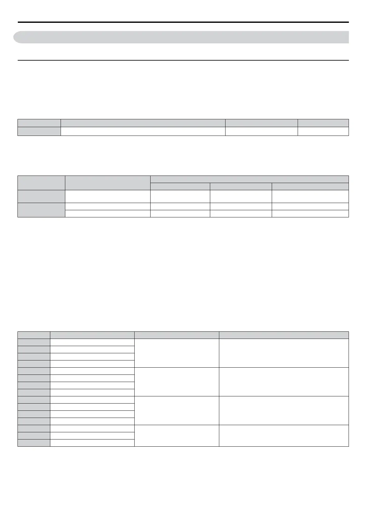
No. Parameter Name Setting Range Default
E1-01
<1>
Input Voltage Setting 155 to 255 V 200 V
<1> The setting range and default value shown here are for 200 V class drives. Double this for 400 V class units.
E1-01 Related Values
The input voltage setting determines the over-/undervoltage detection level and the operation levels of the braking
transistor.
Voltage Setting Value of E1-01
(Approximate Values)
ov Detection Level BTR Operation Level Uv Detection Level
200 V Class all settings 410 V 394 V
190 V
(single-phase = 160 V)
400 V Class
setting ≥ 400 V
820 V 788 V 380 V
setting < 400 V 740 V 708 V 350 V
Note: The braking transistor operation levels are valid for the drive internal braking transistor. If an external CDBR braking chopper is used,
refer to the instruction manual of that unit.
n
V/f Pattern Settings
The drive utilizes a set V/f pattern to determine the appropriate output voltage level for each relative to the frequency
reference.
V/f Pattern Setup for V/f Control
1.
Set the input voltage for the drive. Refer to E1-01: Input Voltage Setting on page 174.
2.
Set the V/f pattern. Refer to V/f Pattern Settings E1-04 to E1-10 on page 174.
n
V/f Pattern Setting Examples
This section provides examples of how to set a V/f pattern using E1-04 to E1-10.
Setting V/f Pattern
Table 5.10 V/f Pattern Examples
Example Specification Characteristic Application
0 50 Hz (default setting)
Constant torque
For general purpose applications. Torque remains
constant regardless of changes to speed.
1 60 Hz
2 60 Hz (with 50 Hz base)
3 72 Hz (with 60 Hz base)
4 50 Hz, Heavy Duty 2
Derated torque
For fans, pumps, and other applications that require torque
derating relative to the load.
5 50 Hz, Heavy Duty 1
6 50 Hz, Heavy Duty 1
7 50 Hz, Heavy Duty 2
8 50 Hz, mid starting torque
High starting torque
Select high starting torque when:
• Wiring between the drive an motor exceeds 150 m
• A large amount of starting torque is required
• An AC reactor is installed
9 50 Hz, high starting torque
10 60 Hz, mid starting torque
11 60 Hz, high starting torque
12 90 Hz (with 60 Hz base)
Constant output
When operating at greater than 60 Hz the output voltage
will be constant.
13 120 Hz (with 60 Hz base)
14 180 Hz (with 60 Hz base)
The following tables show details onV/f patterns.
The following graphs are for 200 V class drives. Double the values when using a 400 V class drive.
5.5 E: Motor Parameters
86
SIEP C710606 33A OYMC AC Drive – J1000 User Manual
 Loading...


