8 Overview of Built-in Functions and Allocations
8-8
CP2E CPU Unit Software User’s Manual(W614)
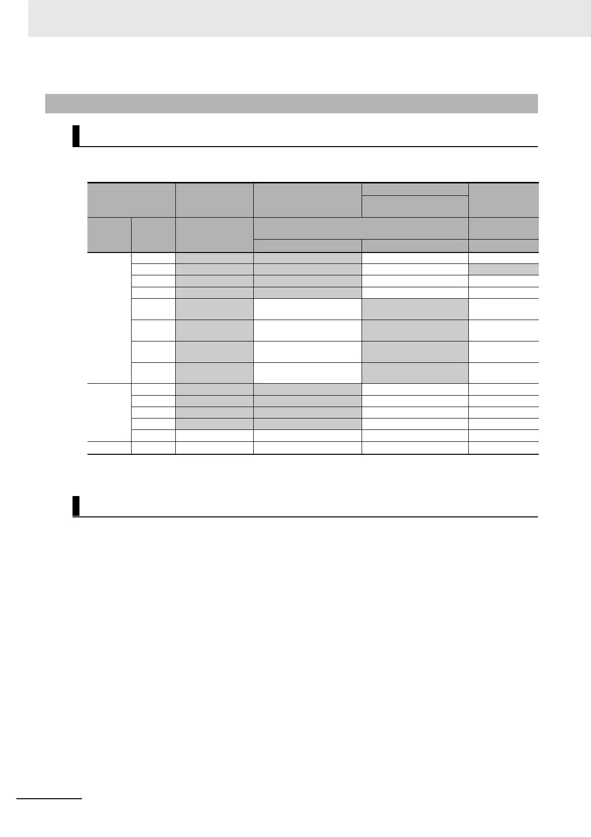
Output terminals are allocated functions by setting parameters in the PLC Setup. Set the PLC Setup so
that each terminal is used for only one function.
Note Only supported by N30/40/60 CPU Units.
The output terminals 00 to 07 of CIO 100 and 00 to 03 of CIO 101 are used for pulse outputs, PWM out-
puts and normal outputs. Therefore, do not use the output terminals repeatedly. For example, if pulse
output 0 (direction) is used, then output terminal 02 is occupied, so it cannot be used for normal output
2.
8-3-4 Allocating Built-in Output Temrinals
Allocating Functions to Built-in Output Terminals
Output terminal block
Other than those
shown at the right
When a pulse output instruc-
tion (ITPL, SPED, ACC, PLS2,
ORG or IFEED) is executed
PLC Setup
When the PWM
instruction is exe-
cuted
Origin search settings on
Pulse Output 0 to 3 Tab Page
Terminal
block label
Terminal
number
Normal outputs
Fixed duty ratio pulse output
Variable-duty-fac-
tor output
Pulse + Direction Mode Use PWM output
CIO 100
00
Normal output 0 Pulse output 0, pulse
−−
01
Normal output 1 Pulse output 1, pulse
−
PWM output 0
02
Normal output 2 Pulse output 0, direction
−−
03
Normal output 3 Pulse output 1, direction
−−
04
Normal output 4
−
Pulse 0, Error counter reset
output
−
05
Normal output 5
−
Pulse 1, Error counter reset
output
−
06
Normal output 6
−
Pulse 2, Error counter reset
output (Note)
−
07
Normal output 7
−
Pulse 3, Error counter reset
output (Note)
−
CIO 101
00
Normal output 8 Pulse output 2, pulse (Note)
−−
01
Normal output 9 Pulse output 3, pulse (Note)
−−
02
Normal output 10 Pulse output 2, direction (Note)
−−
03
Normal output 11 Pulse output 3, direction (Note)
−−
04 to 07
Normal output 12 to 15
−−−
CIO 102
00 to 07
Normal output 16 to 23
−−−
Prohibiting Repeated Use of Output Terminal Number
 Loading...


