13 PWM Outputs
13-4
CP2E CPU Unit Software User’s Manual(W614)
z Pulse Output Port Number and Pulse Output Terminals
The following terminals can be used for pulse outputs according to the pulse output method.
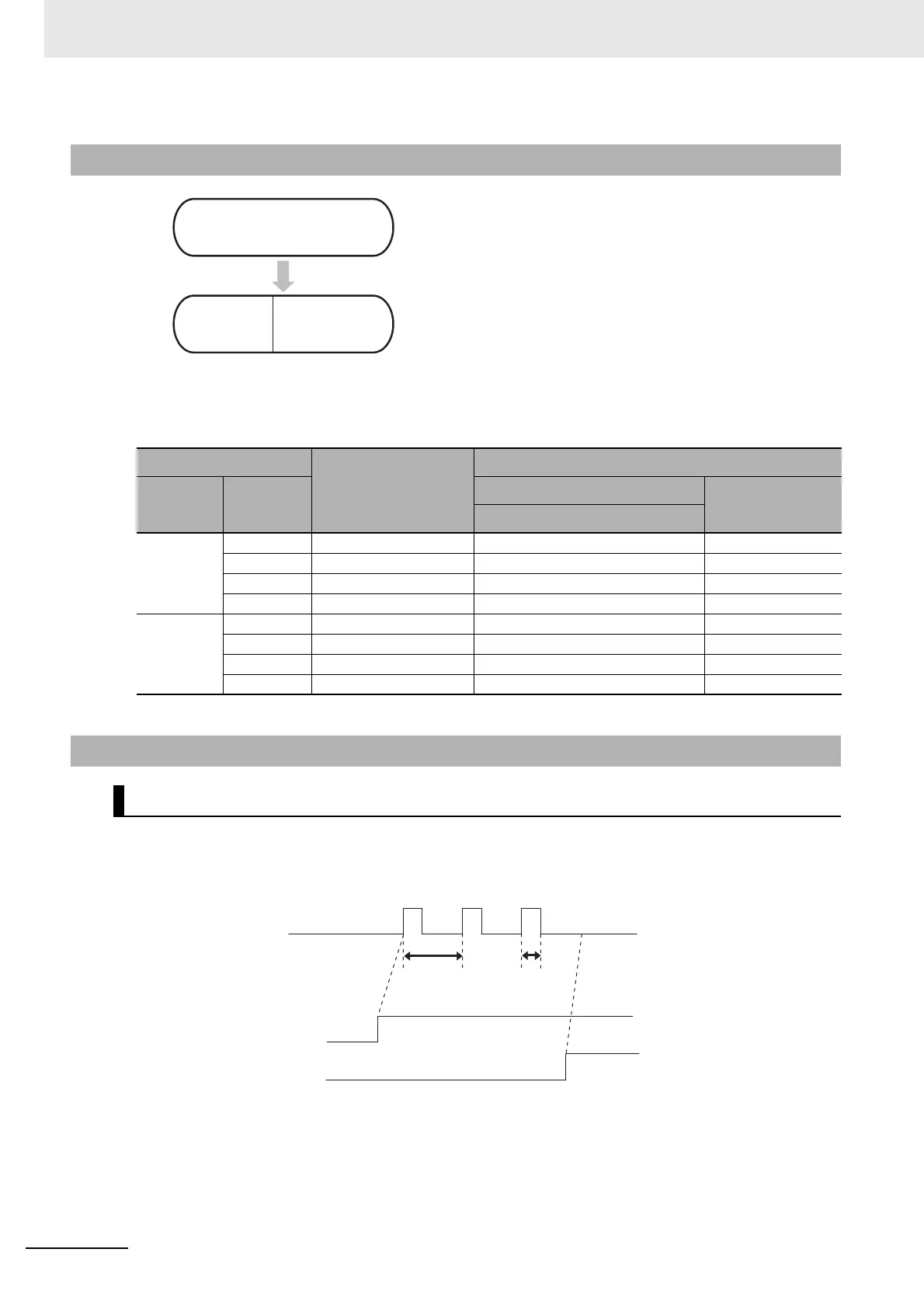
When the start input (CIO 0.00) turns ON in this example, pulses with a duty factor of 40% at a fre-
quency of 2,000 Hz are output from PWM output 0. When the stop input (CIO 0.01) turns ON, PWM
output 0 is stopped.
13-1-1 Flow of Operation
1
2
Terminal 01 on terminal block CIO100 is used for PWM
output 0.
• The PWM instruction is used to control PWM outputs.
• PWM outputs are stopped with the INI instruction.
Output terminal block
Specifications made
with PWM instruction
Other functions that cannot be used at the same time
Terminal
block label
Terminal
number
Pulse output method
Normal output
Pulse + direction
CIO 100 00 − Pulse output 0, pulse Normal output 0
01 PWM output 0 Pulse output 1, pulse Normal output 1
02 − Pulse output 0, direction Normal output 2
03 − Pulse output 1, direction Normal output 3
CIO 101
00 − Pulse output 2, pulse Normal output 8
01 − Pulse output 3, pulse Normal output 9
02 − Pulse output 2, direction Normal output 10
03 − Pulse output 3, direction Normal output 11
13-1-2 Ladder Program Example
Specifications and Operation
Setting pulse output port number,
assigning pulse output terminals,
and wiring.
Greate ladder
program
Cyclic task,
interrupt task.
Start input (CIO 0.00)
Frequency:
2,000 Hz, 500 μs
Stop input (CIO 0.01)
Duty factor:
40%, 200 μs
 Loading...


