17 Analog Input/Output Option Board
17-8
CP2E CPU Unit Software User’s Manual(W614)
17-5 Analog Input Option Board
Each CP1W-ADB21 Analog Input Option Board provides two analog inputs.
• The analog input signal ranges are 0 to 10 V (with a resolution 1/4,000) and 0 to 20 mA (with a reso-
lution 1/2,000).
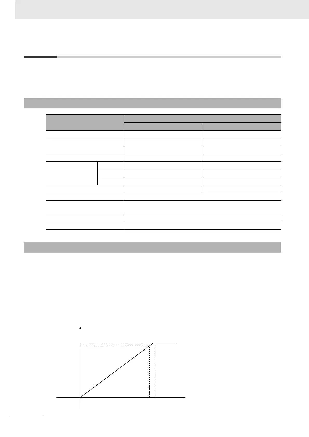
Analog input data is digitally converted according to the input signal range as shown below.
Note When the input exceeds the specified range, the A/D conversion data will be fixed at either the lower limit or
upper limit.
z 0 to 10 V
The 0 to 10 V range corresponds to the hexadecimal values 0000 to 0FA0 (0 to 4000). The entire
data range is 0000 to 0FFF (0 to 4095).
17-5-1 Main Specifications
Item
Specifications
Voltage Input Current Input
Input signal range 0 V to 10 V 0 mA to 20 mA
Max. rated input 0 V to 15 V 0 mA to 30 mA
External input impedance 200 kΩ min. Approx. 250 Ω
Resolution 1/4000 (full scale) 1/2000 (full scale)
Overall accuracy 25°C ±0.5% (full scale) ±0.6% (full scale)
0 to 60°C ±1.0% (full scale) ±1.2% (full scale)
-20 to 0°C ±1.3% (full scale) ±1.5% (full scale)
A/D conversion data 0000 to 0FA0 hex 0000 to 07D0 hex
Averaging function Not supported
Conversion time Inner sample time 2ms/point
Refresh time refers to 17-9 Analog Option Board Refresh Time
Isolation method None
Current consumption 5 VDC: 20 mA max.
17-5-2 Analog Input Signal Ranges
Converted Data
Hexadecimal (Decimal)
10V 10.24V
0FA0(4000)
0FFF(4095)
0000(0)
0V
 Loading...


