EasyManua.ls Logo

Omron SYSMAC CP2E-E D Series User Manual

Omron SYSMAC CP2E-E D Series
578 pages
To Next Page IconTo Next Page
To Previous Page IconTo Previous Page
Page #559 background imageLoading...
Page #559 background image
A-99
Appendices
CP2E CPU Unit Software User’s Manual(W614)
A-3 Response Performance
App
A-3-1 I/O Response Time
A-3 Response Performance
The I/O response time is the time it takes from when an input turns ON, the data is recognized by the
CPU Unit, and the ladder programs are executed, up to the time for the result to be output to an output
terminal.
The length of the I/O response time depends on the following conditions.
Timing of Input Bit turning ON.
The cycle time
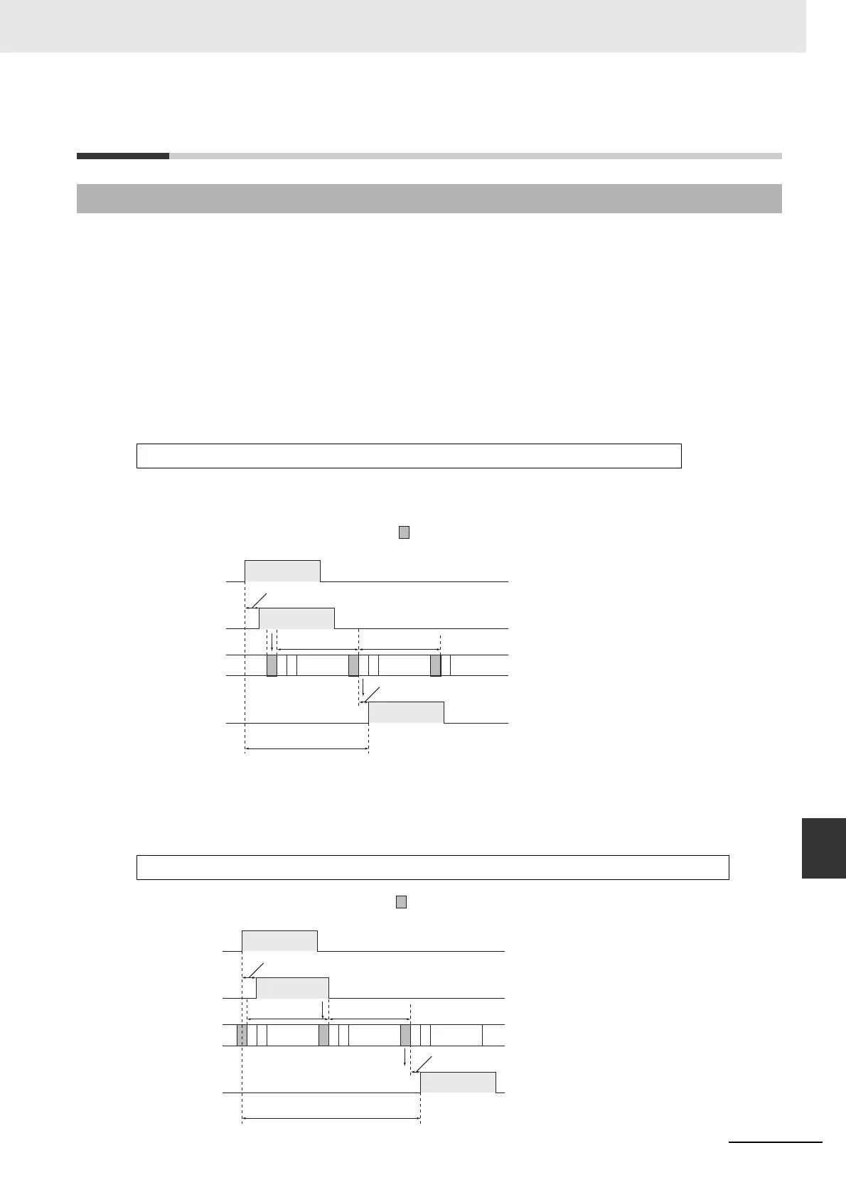
z Minimum I/O Response Time
The I/O response time is shortest when data is retrieved immediately before I/O refresh of the CPU Unit.
The minimum I/O response time is calculated as follows:
Note The input and output ON delays depend on the type of terminals used on the CPU Unit or the model number
of the Unit being used.
z Maximum I/O Response Time
The I/O response time is longest when data is retrieved immediately after I/O refresh period of the
CPU Unit.
The maximum I/O response time is calculated as follows:
A-3-1 I/O Response Time
Minimum I/O response time = Input ON delay + Cycle time + Output ON delay
Maximum I/O response time = Input ON delay + (Cycle time × 2) + Output ON delay
Inputs:
Outputs:
:I/O refresh
Input ON delay
Cycle time Cycle time
Output ON delay
Minimum I/O
Response Time
(Status read to
the CPU Unit.):
Instruction
execution
Instruction
execution
Inputs:
Outputs:
:I/O refresh
Input ON delay
Cycle time Cycle time
Output ON delay
Maximum I/O Response Time
(Status read to
the CPU Unit.):
Instruction
execution
Instruction
execution
Instruction
execution

Table of Contents

Question and Answer IconNeed help?

Do you have a question about the Omron SYSMAC CP2E-E D Series and is the answer not in the manual?

Omron SYSMAC CP2E-E D Series Specifications

General IconGeneral
Input Voltage24V DC
Data MemoryUp to 32 KB
TypeProgrammable Logic Controller (PLC)
CPU TypeRISC
Communication PortsRS-232C, RS-485
Ethernet PortYes
USB PortYes
Serial Port1 x RS-232C
High-speed CounterYes
Pulse OutputYes
Interrupt InputsYes (4 inputs)
Expansion Slots2
Operating Temperature0°C to 55°C
Dimensions90 x 90 x 70 mm
SeriesCP2E-E D Series

Summary

SYSMAC CP Series

CP2E CPU Unit Software User’s Manual

User's Manual for CP2E CPU Unit Software.

Introduction

CP2E CPU Unit Manuals

CP2E CPU Unit Software User’s Manual (This Manual)

Describes software specifications, operation, memory, programming, and functions.

CONTENTS

Safety Precautions

Provides critical safety information for using the PLC.

Precautions for Safe Use

Details precautions for handling and external circuits for safe operation.

Section 2 Internal Memory in the CPU Unit

Details the types of internal memory and stored data in the CPU Unit.

Section 3 CPU Unit Operation

Explains CPU Unit operation, modes, and behavior during power interruptions.

Section 4 Understanding Programming

Covers basic information on ladder programming for CP2E CPU Units.

4 Understanding Programming

4-1 Programming

Covers user programs, data, and programming languages.

4-4 Programming Instructions

Details instructions, operands, variations, execution conditions, data formats, and I/O refresh.

Section 5 I/O Memory

Describes the types of I/O memory areas and their details.

Section 7 PLC Setup

Details parameters for basic settings of the CP2E CPU Unit.

7 PLC Setup

7-2 PLC Setup Settings

Covers settings for startup, timing, interrupts, inputs, and outputs.

7-2 PLC Setup Settings

Covers settings for startup, timing, interrupts, inputs, serial ports, pulse outputs, and Ethernet.

Terms and Conditions Agreement

Warranty, Limitations of Liability

Outlines warranty, limitations of liability, and buyer remedies.

Limitation on Liability; Etc

States OMRON COMPANIES SHALL NOT BE LIABLE FOR SPECIAL, INDIRECT, INCIDENTAL DAMAGES.

Precautions for Safe Use

Handling

Precautions for proper unit setting, DIP switches, DM Area initialization, and program checks.

Related Manuals

SYSMAC CP Series CP2E CPU Unit Software User’s Manual (this manual)

Describes software specifications, CPU Unit operation, programming, and functions.

1 Overview

1-2 Basic Operating Procedure

Outlines the general procedure for setting up and operating the CP2E.

2 Internal Memory in the CPU Unit

2-1 Internal Memory in the CPU Unit

Details the types of internal memory and stored data in the CPU Unit.

3 CPU Unit Operation

3-1 CPU Unit Operation

Describes CPU Unit operation, modes, and behavior during power interruptions.

3-2 Backing Up Memory

Explains data backup to built-in Flash Memory and non-volatile RAM.

5 I/O Memory

5-1 Overview of I/O Memory Areas

Describes I/O memory areas: CIO, Work, Holding, Data, Timer, Counter, Index, Data Registers, System Areas.

6 I/O Allocation

6-1 Allocation of Input Bits and Output Bits

Explains OMRON's term for allocating I/O bits and how the CPU Unit allocates them to expansion units.

8 Overview of Built-in Functions and Allocations

8-2 Overall Procedure for Using CP2E Built-in Functions

Describes the steps to select, configure, create programs, transfer, and start using functions.

9 Quick-response Inputs

10 Interrupts

10-2 Input Interrupts

Explains input interrupts that execute tasks when built-in inputs turn ON or OFF.

11 High-speed Counters

11-1 Overview

Describes using high-speed counters for measuring pulse input signals and applications.

11-2 High-speed Counter Inputs

Details pulse input methods, counting ranges, reset methods, and frequency measurement.

11-3 High-speed Counter Interrupts

Explains executing interrupt tasks based on counter PV comparison with target values or ranges.

12 Pulse Outputs

12-2 Positioning Control

Describes using pulse outputs with trapezoidal acceleration/deceleration.

12-6 Defining Origin Position

Describes methods to define origin position using origin search or PV changes.

13 PWM Outputs

13-1 PWM Outputs (Variable-duty-factor Pulse Outputs)

Describes PWM outputs, including application examples and specifications.

14 Serial Communications

14-4 Modbus-RTU Easy Master Function

Explains using Modbus-RTU Easy Master for controlling Modbus-compatible slaves.

14-7 Modbus-RTU Slave Function

Explains reading and writing CP2E data from Modbus-compatible masters.

15 Ethernet

15-3 Basic Setting for Ethernet

Outlines the startup procedure, PLC setup, basic settings, and communications test.

15-4 FINS Communications

Explains FINS communication services, procedures, and PLC setup for UDP and TCP.

16 Other Functions

16-1 PID Temperature Control

Explains PID instructions with autotuning for temperature control.

16-3 DM Backup Function

Describes saving specified DM Area words to built-in Flash Memory and automatic restoration.

18 Programming Device Operations

18-3 Creating a Ladder Program

Details inputting, saving, reading, editing ladder programs, and using automatic creation.

18-4 Connecting Online to the CP2E and Transferring the Program

Explains making an online connection and transferring programs.

18-5 Online Monitoring and Debugging

Describes monitoring status, force-set/reset bits, and online editing.

Related product manuals