11-11
11 High-speed Counters
CP2E CPU Unit Software User’s Manual(W614)
11-2 High-speed Counter Inputs
11
11-2-3 Reset Methods
Input pulses are counted in a loop within the set range.
• If the count is incremented from the maximum ring count, the count will be reset to 0 automatically
and incrementing will continue.
• If the count is decremented from 0, the count will be set to the maximum ring count automatically and
decrementing will continue.
Consequently, underflows and overflows cannot occur when Ring Mode is used.
z Maximum Ring Count
Use the PLC Setup to set the maximum ring count (Circular Max. Count), which is the maximum
value of the input pulse counting range. The maximum ring count can be set to any value between
0000 0001 and FFFF FFFF hex (1 to 4,294,967,295 decimal).
Precautions for Correct UsePrecautions for Correct Use
• There are no negative values in Ring Mode.
• If the maximum ring count is set to 0 in the PLC Setup, the counter will operate with a maxi-
mum ring count of FFFF FFFF hex.
It is called reset that a high-speed counter’s PV is set to 0.
There are two reset methods
• Phase-Z signal + software reset
• software reset
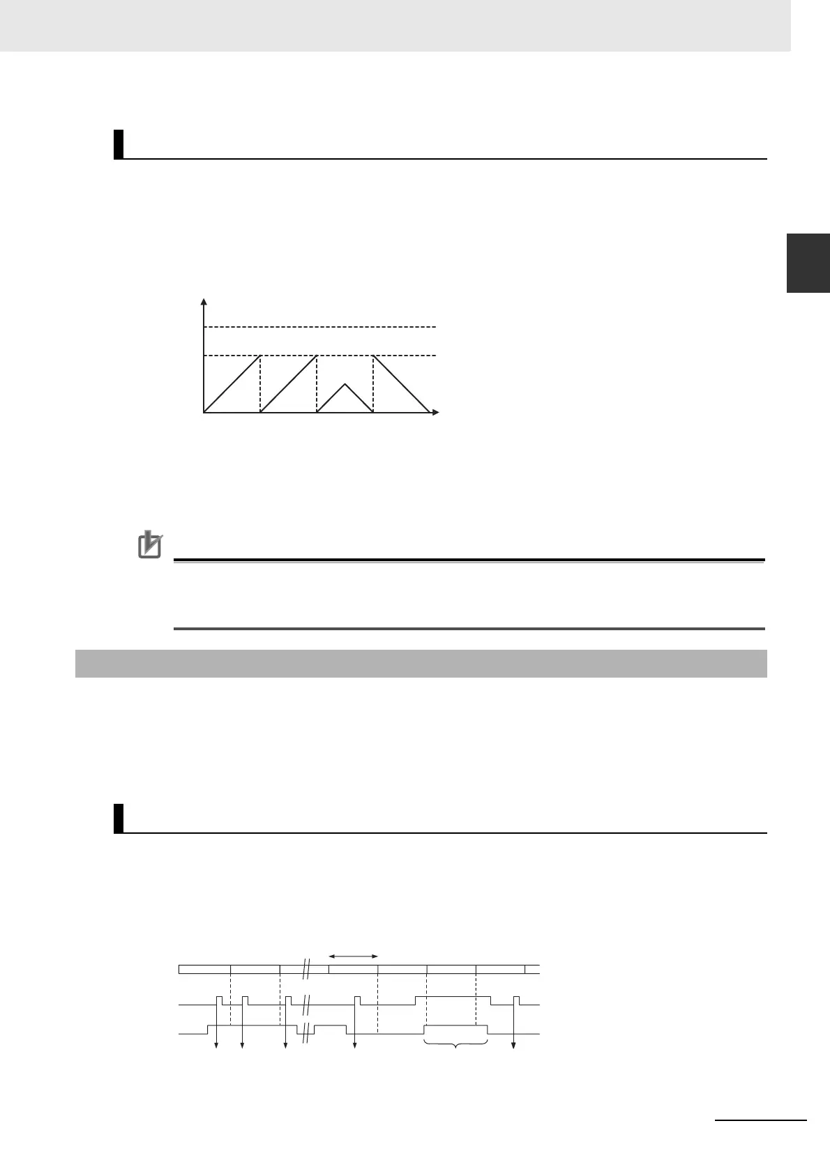
The high-speed counter’s PV is reset when the phase-Z signal (reset input) goes from OFF to ON while
the corresponding High-speed Counter Reset Bit (A531.00 to A531.05) is ON.
The CPU Unit recognizes the ON status of the High-speed Counter Reset Bit only at the beginning of
the PLC cycle during the overseeing processes. Consequently, when the Reset Bit is turned ON in the
ladder program, the phase-Z signal does not become effective until the next PLC cycle.
Note The phase-Z signal cannot be used if an incremental counter is specified. Only a software reset can be used.
Circular (Ring) Mode
11-2-3 Reset Methods
Phase-Z Signal + Software Reset
0
2
32
-1
Maximum ring
count
Count value
One cycle
Phase Z
Reset bit
PV not
reset
PV not resetPV reset PV reset PV reset PV reset