17-25
17 Analog Input/Output Option Board
CP2E CPU Unit Software User’s Manual(W614)
17-11 The Use of Analog Option Board
17
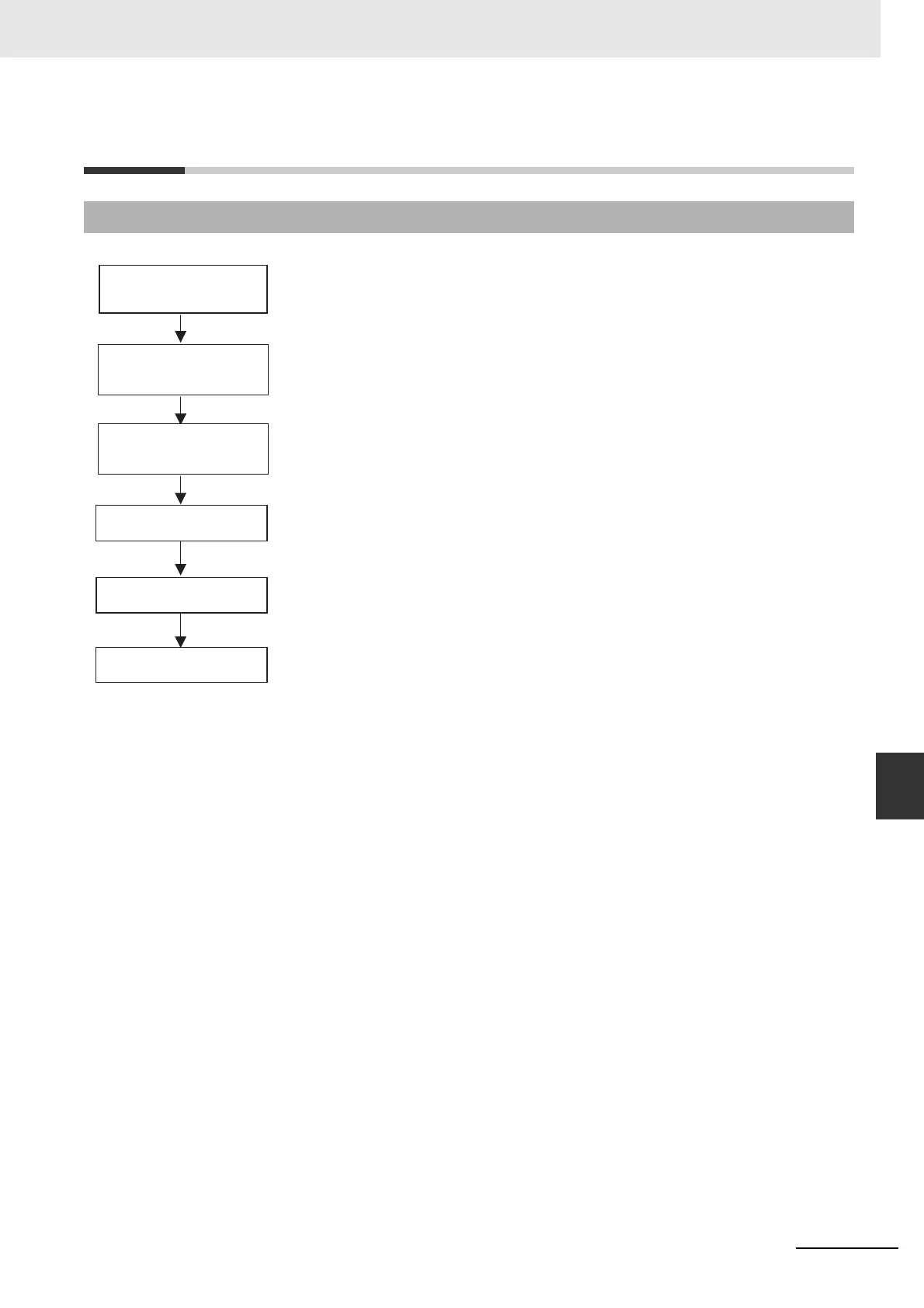
17-11-1 Procedure
17-11The Use of Analog Option Board
17-11-1 Procedure
Connection with the analog
input/output device
Make the ladder program
Connection with the analog
input/output device
Mount the Analog Option
Board
Restart the CPU Unit
AD/DA convert
Mount the Analog Option Board into the option port.
Connect to the analog input/output device.
Set communication protocol in PLC Settings to Host Link, 115200bps, 7,2,E.
Turn the power of the CPU Unit OFF and ON again.
Wait until the Analog Option Board finishes initialization and works normally.
Read the analog input data/write the analog output data.
Note 1 If PLC communication protocol setting is error, the option board will always try to link the PLC, and the
error LED will be lit.
2 Only when the initialization process has finished (A435.15 sets on), user can use the A/D conversion
data or write the D/A output data.
 Loading...


