11 High-speed Counters
11-10
CP2E CPU Unit Software User’s Manual(W614)
Additional Information
The count of a high-speed counter can be monitored to see if it is currently being incremented or
decremented. The count in the current cycle is compared with the count in the previous cycle to
determine if it is being incremented or decremented.
The results are reflected in the High-speed Counter Count Direction Flags.
The following counting modes can be selected for high-speed counters: Linear Mode that counts in a
fixed range and Circular (Ring) Mode that counts in a set range of any maximum value.
Input pulses can be counted in the range between the lower limit and upper limit values. If the pulse
count goes beyond the lower/upper limit, an underflow/overflow will occur and counting will stop.
• Increment Mode
• Up/Down Mode
High-speed counter
Address of High-speed
Counter Count Direction Flag
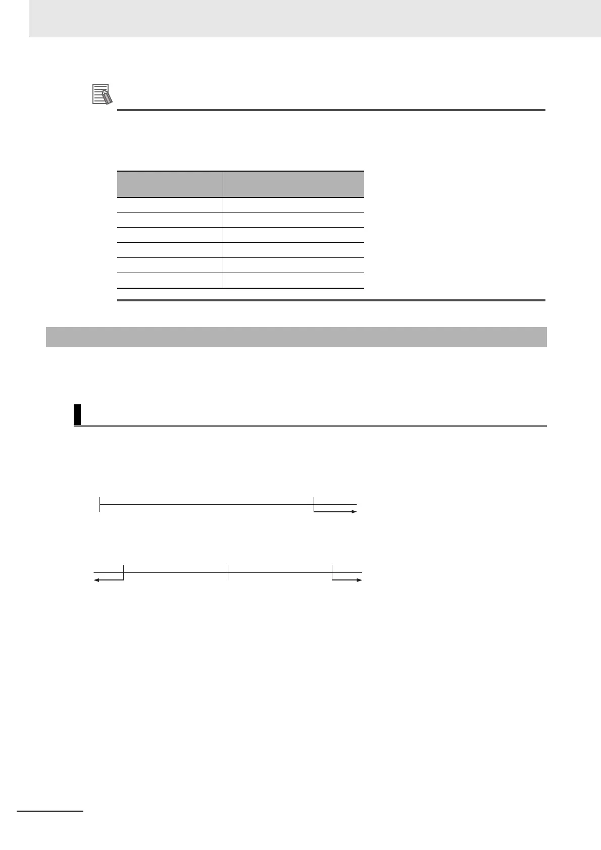
High-speed counter 0 A274.10
High-speed counter 1 A275.10
High-speed counter 2 A320.10
High-speed counter 3 A321.10
High-speed counter 4 A326.10
High-speed counter 5 A327.10
11-2-2 Counting Ranges Settings
Linear Mode
0
(000000 Hex)
4294967295
(FFFFFFFF Hex)
PV overflow
+2147483647
(7FFFFFFF Hex)
-2147483648
(80000000 Hex)
0
(00000000 Hex)
PV underflow PV overflow
 Loading...


