15 Ethernet
15-42
CP2E CPU Unit Software User’s Manual(W614)
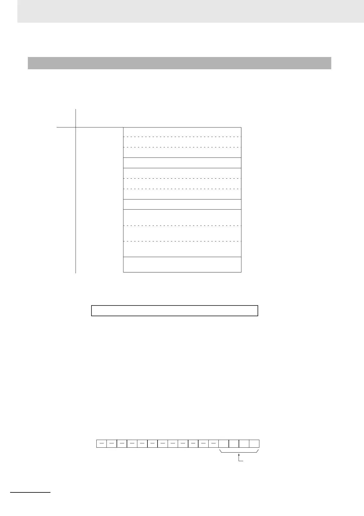
The memory allocation about socket service is shown in the following diagram. These data will be allo-
cated to the DM area of the PLC.
Beginning word m = 16000
z TCP Socket No. (1 to 3): Number of Bytes Received
For each TCP socket, the number of bytes of data in the reception buffer is stored in one word. A max-
imum of 4,096 bytes of data can be held in the reception buffer, but a value of only up to the maximum
value (1,024 bytes) that can be set for receive requests by manipulating control bits is stored.
0000 hex: 0 bytes
0400 hex: 1,024 bytes
The Data Received Flag in the CIO Area turns ON and OFF linked to this word. This area is given a
value of 0000 hex when a receive request is executed by manipulating control bits. If any data
remains in the reception buffer after the receive request processing is completed, the remaining
number of bytes is stored and the Data Received Flag turns ON again.
Before a receive request is executed, a check is performed to confirm that the required data is avail-
able.
z TCP Socket No. (1 to 3): Connection Status
The connection status for each TCP socket is stored by code in this word. For details, refer to A-6-1
TCP Status Tr a n sitions.
15-5-6 Data Memory Area Allocations
Word
Bit
D16000
D16001
D16002
D16004
D16005
D16006
D16007
D16008 to D16017
D16018 to D16027
D16028 to D16037
D16038 to D16047
Offset
m
m+1
m+2
m+4
m+5
m+6
m+7
m+8
m+17
m+18
m+27
m+28
m+37
m+38
m+47
15 08 07 00
TCP Socket No. 1 Connection Status
TCP Socket No. 2 Connection Status
TCP Socket No. 3 Connection Status
Socket Services Parameter Area 1
Socket Services Parameter Area 2
Socket Services Parameter Area 3
Reserved
TCP Socket No. 1 Number of Bytes Received
TCP Socket No. 3 Number of Bytes Received
Reserved
TCP Socket No. 2 Number of Bytes Received
D16003m+3 Reserved
m to m+2 Number of Bytes Received (0000 to 0400 hex)
1514131211109876543210
TCP connection status
15 14 13 12 11 10 9 8 7 6 5 4 3 2 1 0
m+4 to m+6
 Loading...


