Appendices
A-100
CP2E CPU Unit Software User’s Manual(W614)
z Calculation Example
Conditions:
Input ON delay: 1 ms (normal input 0.08 to 0.11 with input constant set to 0 ms)
Output ON delay: 0.1 ms (transistor output)
Cycle time: 20 ms
Minimum I/O response time = 1 ms + 20 ms + 0.1 ms = 21.1 ms
Maximum I/O response time = 1 ms + (20 ms × 2) + 0.1 ms = 41.1 ms
Input constant setting can be set in the PLC Setup.
Increasing the input constants slowers the input response time and reduces the effects of chattering
and noise. Decreasing the input constants fasters the input response time and allows reception of
shorter input pulses (but the pulse width must be longer than the cycle time).
z PLC Setup
Note The input constants of CP1W-40EDR/EDT/EDT1 are always 16ms regardless of the settings.
Input Constant Setting
Name Description Setting Default
Input Constant Settings Input Constants 00 hex: 8 ms
10 hex: No filter (0 ms)
12 hex: 1 ms
13 hex: 2 ms
14 hex: 4 ms
15 hex: 8 ms
16 hex: 16 ms
17 hex: 32 ms
00 hex (8 ms)
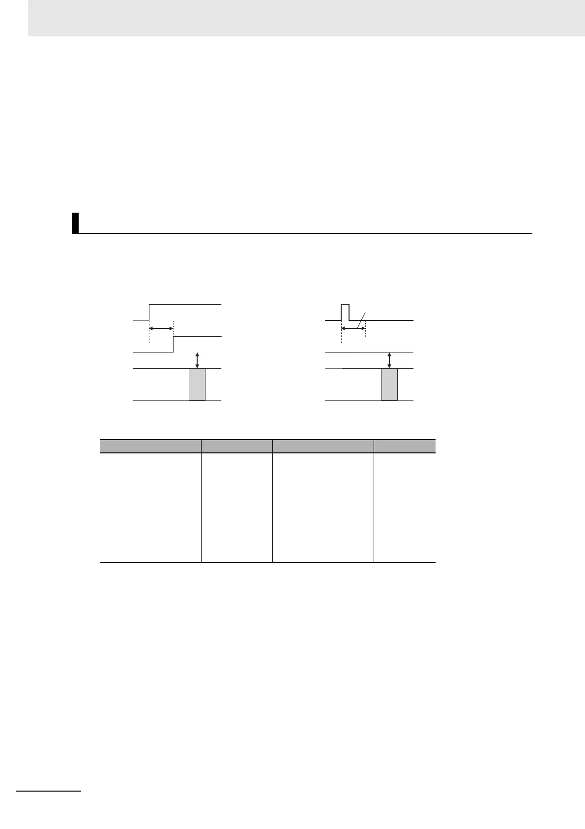
Input response time
Input response time
I/O refresh
I/O refresh
Inputs Inputs
CPU Unit CPU Unit
Pulses shorter than the input
response time are not received
 Loading...


