13-5
13 PWM Outputs
CP2E CPU Unit Software User’s Manual(W614)
13-1 PWM Outputs (Variable-duty-factor Pulse Outputs)
13
13-1-2 Ladder Program Example
PWM
INI
z PLC Setup
There are no settings that need to be made in the PLC Setup.
z DM Area Settings
• PWM Operand Settings (D0 and D1)
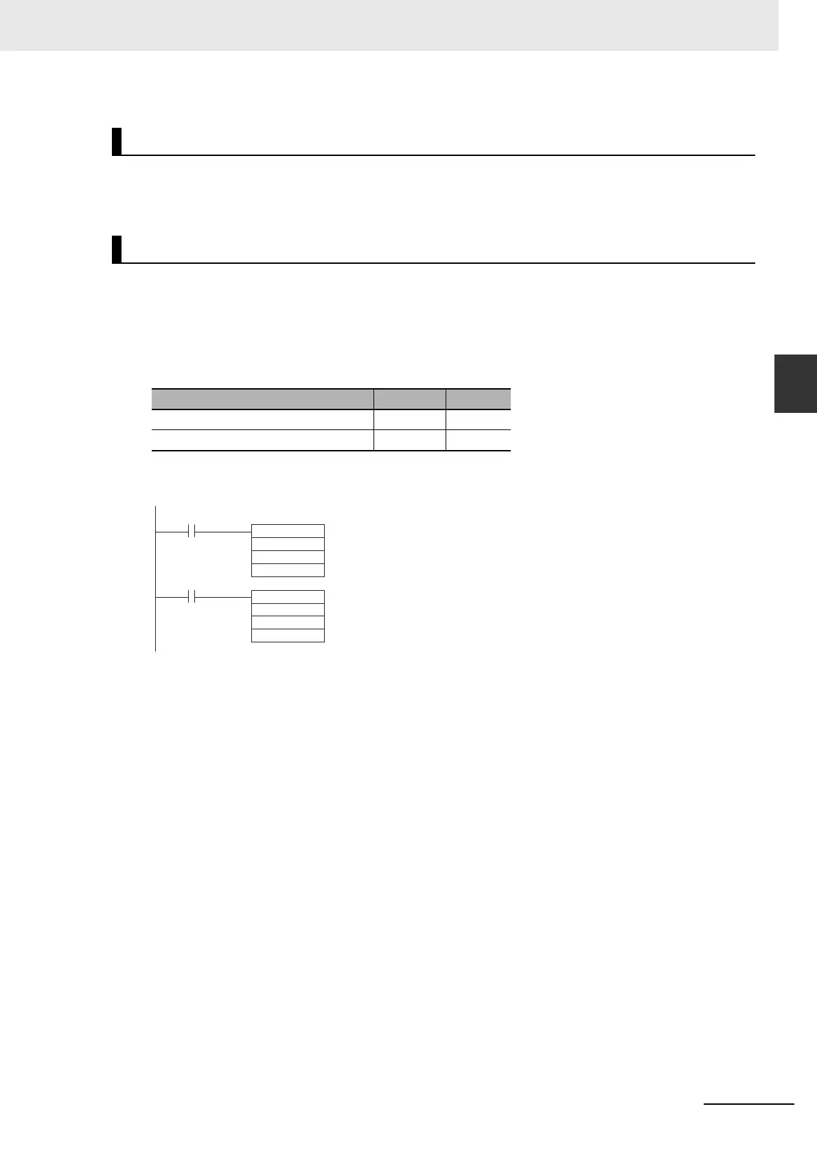
z Ladder Diagram
Applicable Instructions
Preparations
Setting Operand Data
Frequency: 2,000.0 Hz D0 #4E20
Duty factor: 40.0% D1 #0190
@PWM
#1000
D0
D1
#1000
#0003
D10
0.00
0.01
Start input
Stop input
←PWM output 0 (Duty factor in increments of 0.1%, Frequency in increments of 0.1 Hz)
←Frequency setting
←Duty factor setting
←PWM output 0
←Stops pulse output
←Not used.
@INI
 Loading...


