10-5
10 Interrupts
CP2E CPU Unit Software User’s Manual(W614)
10-2 Input Interrupts
10
10-2-2 Flow of Operation
Built-in Input Tab Page
Note 1 The power supply must be restarted after the PLC Setup is transferred in order to enable the interrupt
input settings.
2 IN8 and IN9 are only supported by N20/30/40/60 CPU Units.
The following input terminals can be used for interrupt inputs. These terminals correspond to CIO 0.02
to CIO 0.09 in I/O memory.
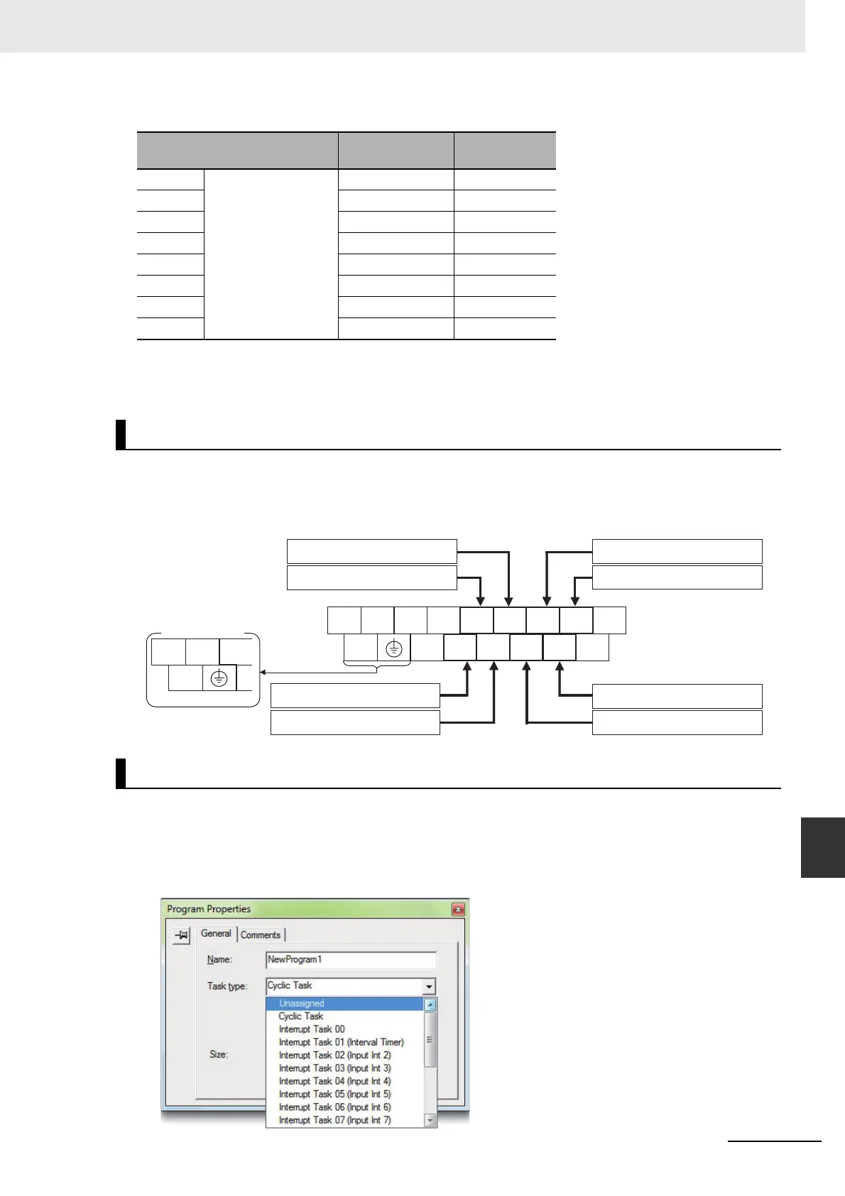
z Input Terminal Block on CPU Unit with 20 I/O Points
z Writing the Interrupt Task’s Ladder Program
Create ladder programs for interrupt tasks 2 to 9, which are executed for the corresponding interrupt
inputs. Right-click a program in the CX-Programmer and select Properties. Select interrupt tasks 2
to 9 in the Task Type Field of the Program Properties Dialog Box.
Interrupt input settings
Corresponding
bit address
Input interrupt
task
IN2 Select Interrupt for
IN2 to IN9.
CIO 0.02 2
IN3 CIO 0.033
IN4 CIO 0.04 4
IN5 CIO 0.05 5
IN6 CIO 0.06 6
IN7 CIO 0.07 7
IN8 CIO 0.088
IN9 CIO 0.09 9
Assigning Interrupt Input Terminals
Writing the Ladder Program
L1 L2/N COM 01 03 05 07 09 11
NC 00 02 04 06 08 10
Upper Terminal Block
Interrupt input IN5: CIO 0.05
Interrupt input IN3: CIO 0.03
Interrupt input IN7: CIO 0.07
Interrupt input IN9: CIO 0.09
Interrupt input IN6: CIO 0.06
Interrupt input IN8: CIO 0.08
Interrupt input IN2: CIO 0.02
Interrupt input IN4: CIO 0.04
CIO 0
COM
+
-
NC
DC Power Supply
 Loading...


