14 Serial Communications
14-38
CP2E CPU Unit Software User’s Manual(W614)
z PLC Setup
z Programming Example
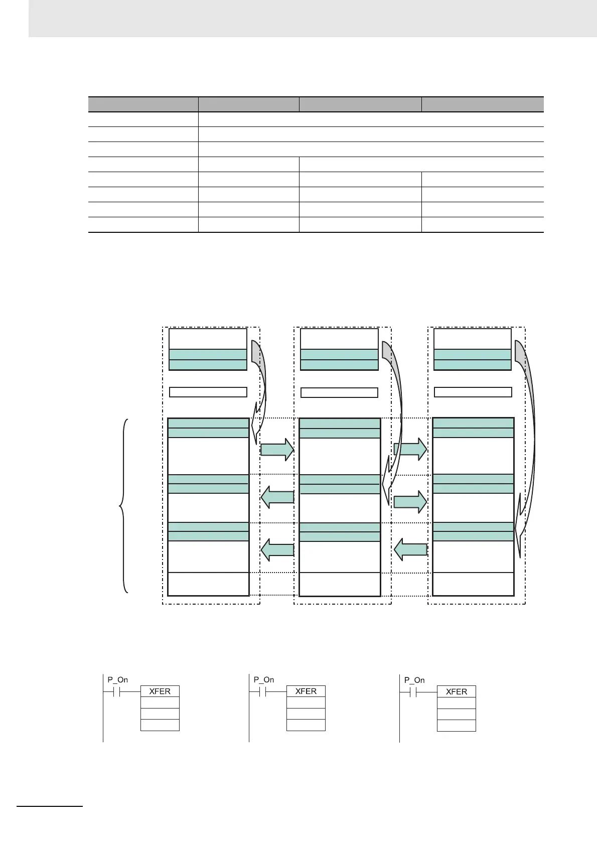
Data in the Serial PLC Link Areas are transferred using data links by the Serial PLC Link and without
using any special programming. The ladder program is used to transfer the data that needs to be
linked to the data link area.
z Ladder Diagram
Item Boiler A (Polling Unit) Boiler B (Polled Unit No. 0) Boiler C (Polled Unit No. 1)
Communications Settings Custom
Baud Rate 115200bps
Parameters 7.2.E (default)
Mode PC Link (Master) PC link (Slave)
Link words 10 (default) −−
PC Link Mode ALL −−
NT/PC Link Max. 1 −−
PC Link Unit No. − 01
Boiler A
CP2E (Polling Unit)
Boiler B
CP2E (Polled Unit No.1)
Boiler C
CP2E (Polled Unit No. 0)
Input Bits Input Bits Input Bits
A_Temperature data 0
A_Temperature data 1
A_Temperature data 0
A_Temperature data 1
B_Temperature data 0
B_Temperature data 1
C_Temperature data 0
C_Temperature data 1
A_Temperature data 0
A_Temperature data 1
B_Temperature data 0
B_Temperature data 1
C_Tempera
ture data 0
C_Temperature data 1
A_Temperature data 0
A_Temperature data 1
B_Temperature data 0
B_Temperature data 1
C_Temperature data 0
C_Temperature data 1
B_Temperature data 0
B_Temperature data 1
C_Temperature data 0
C_Tempera
ture data 1
Output Bits Output Bits
Output Bits
CIO 0
CIO 1
CIO 2
CIO 3
CIO 100
CIO 200
CIO 201
CIO 209
CIO 210
CIO 211
CIO 219
CIO 220
CIO 221
CIO 229
CIO 289
Serial PLC
Link Areas
#2
2
200
#2
2
210
#2
2
220
Boiler A
CP2E CPU Unit
(Polling Unit)
Transfer CIO 2 and CIO 3 to
CIO 200 and CIO 201 using a
BLOCK TRANSFER instruction.
Boiler B
CP2E CPU Unit
(Polled Unit No. 0)
Transfer CIO 2 and CIO 3 to
CIO 210 and CIO 211 using a
BLOCK TRANSFER instruction.
Boiler C
CP2E CPU Unit
(Polled Unit No. 1)
Transfer CIO 2 and CIO 3 to
CIO 220 and CIO 221 using a
BLOCK TRANSFER instruction
 Loading...


