15 Ethernet
15-14
CP2E CPU Unit Software User’s Manual(W614)
Note 1 Make settings using the PLC settings function in the CX-Programmer (to be included in version 9.72 and
higher).
2 For details, refer to 2-9 Basic Settings in the Ethernet Units Construction of Networks Operation Manual
(Cat. No. W420).
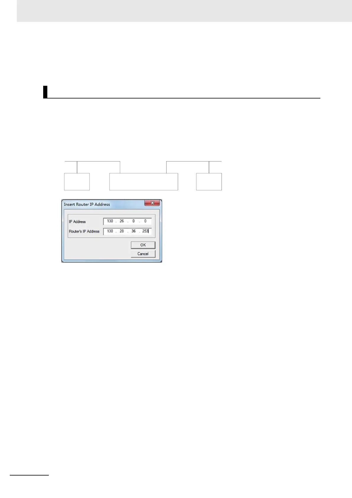
An IP router table is a table of correspondences for finding IP addresses for the IP routers that relay tar-
get segments when the Unit communicates via IP routers with nodes on other IP network segments.
z Setting Example
In this example setting for Node A, a network with a Network ID of 130.26.1.1 is connected to an IP
router with an IP address of 130.28.36.253.
Set the IP Address to the network number (i.e., the net ID) of the other IP network segment with
which communications are to be executed. The length of the network number (i.e., the number of
bytes) will vary depending on the IP address class. Four bytes are reserved for setting the IP
Address, so set the network number from the beginning and then set 00 in the remaining space.
A maximum of eight settings can be registered. The default is no setting.
Only one default IP router can be set.
The default IP router is selected when no Network ID exists in the IP router table for the destination
network number. To set the default IP router, set 0.0.0.0 for the IP address and set the default IP
router's IP address for the router address.
IP Router Table
130.28.XX (Network ID) 130.26.XX (Network ID)
130.28.36.253 130.26.2.254
IP router
Node A
130.26.1.1
CP2E-N
 Loading...


