A-53
Appendices
CP2E CPU Unit Software User’s Manual(W614)
A-1 Instruction Functions
App
A-1-20 Basic I/O Unit Instructions
7-SEGMENT
DISPLAY OUT-
PUT
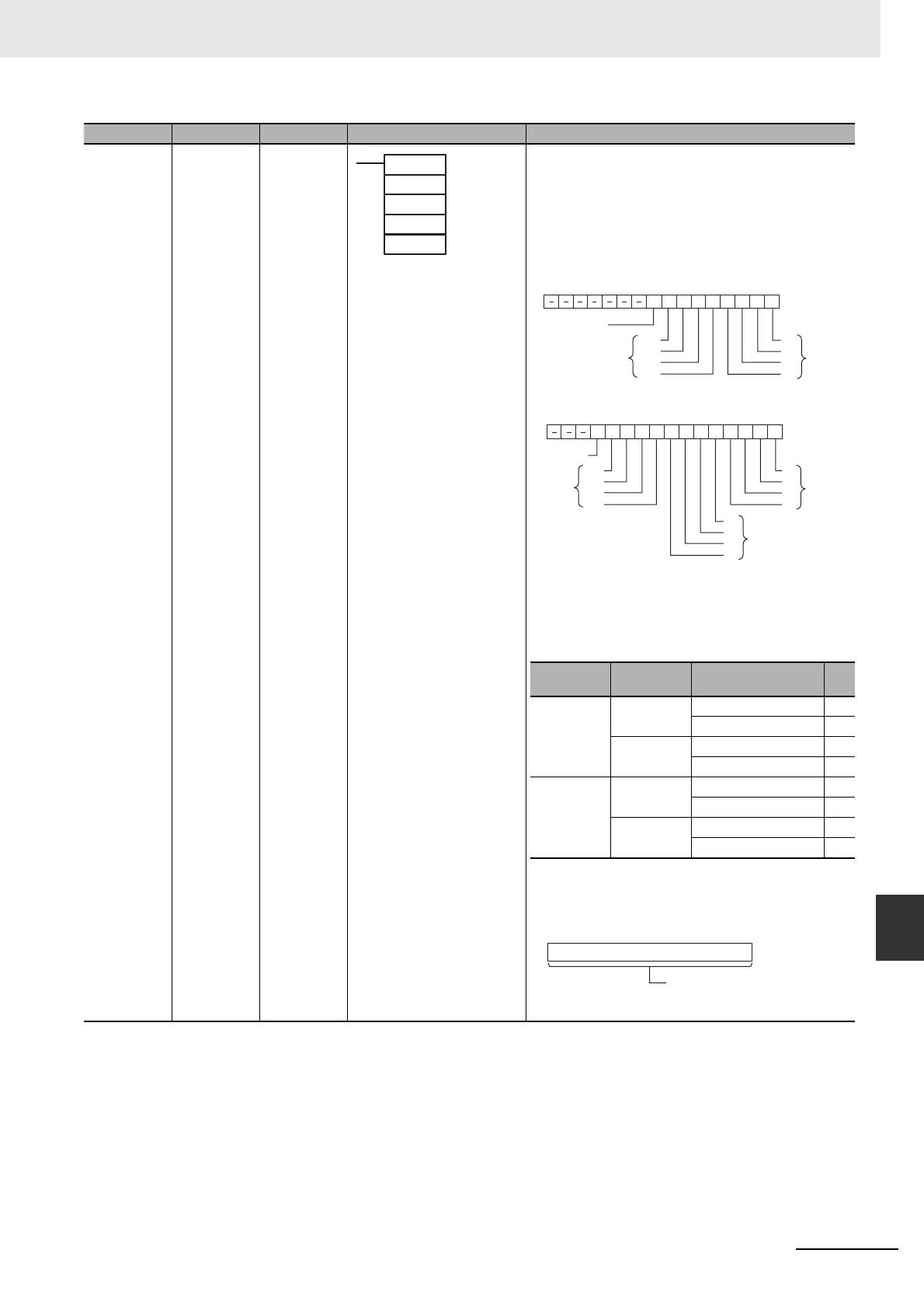
7SEG --- Converts the source data (either 4-digit or 8-digit BCD) to 7-seg-
ment display data, and outputs that data to the specified output
word.
O: Output Word (Data and Latch Outputs)
Specify the output word allocated to the Output Unit and con-
nect the 7-segment display to the Output Unit as shown in the
following diagram.
• Converting 4 digits
• Converting 8 digits
C: Control Data
The value of C indicates the number of digits of source data
and the logic for the Input and Output Units, as shown in the fol-
lowing table. (The logic refers to the transistor output’s NPN or
PNP logic.)
D: System Word
Specifies a work word used by the instruction. This word can-
not be used in any other application.
Instruction Mnemonic Variations Symbol/Operand Function
7SEG (214)
S
O
C
D
S: 1st source word
O: Output word
C: Control data
D: System word
0123456789101112131415
O
D0
D1
D2
D3
LE3
LE2
LE1
LE0
4-digit data
output
Latch outputs
One Round Flag
0123456789101112131415
O
D0
D1
D2
D3
LE3
LE2
LE1
LE0
D0
D1
D2
D3
Leftmost
4-digit data
output
Rightmost 4-digit
data output
Latch
outputs
One Round
Flag
Source data
Display’s data
input logic
Display’s latch input logic C
4 digits (S) Same as Out-
put Unit
Same as Output Unit 0000
Different from Output Unit 0001
Different from
Output Unit
Same as Output Unit 0002
Different from Output Unit 0003
8 digits (S, S+1) Same as Out-
put Unit
Same as Output Unit 0004
Different from Output Unit 0005
Different from
Output Unit
Same as Output Unit 0006
Different from Output Unit 0007
D
15 0
System word
(Cannot be accessed by the user.)
 Loading...


