5.64
BODY / STEERING / SUSPENSION
9924125 - 2013 RANGER RZR / RZR S / RZR 4 Service Manual
© Copyright 2012 Polaris Sales Inc.
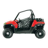
19. Push the IFP out of the shock body. Note the
orientation of the IFP as the relief contour must face
the shock shaft assembly during installation (Fig. 8).
20. Mount the shock rod assembly eyelet in a bench vise.
Remove t
he lock nut.
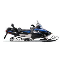
21. Remove the rebound valve stack. Z
ip tie the valves
together (Fig. 9).
22. Remove the piston/wear band (if still attached).
Disca
rd wear band. Note the orientation of the
rebound and compression sides of the piston.
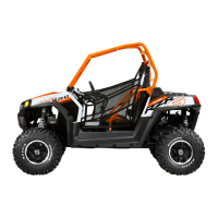
23. Remove the compression valve stack (Fig. 10). Zip tie
th
e valves together. Note that the valve shim closest
to the piston is ported. This is the air bleed valve shim.
24. Remove the bearing cap, body cap, and bumper.
D
iscard all o-rings. Inspect bumper and replace as
required.
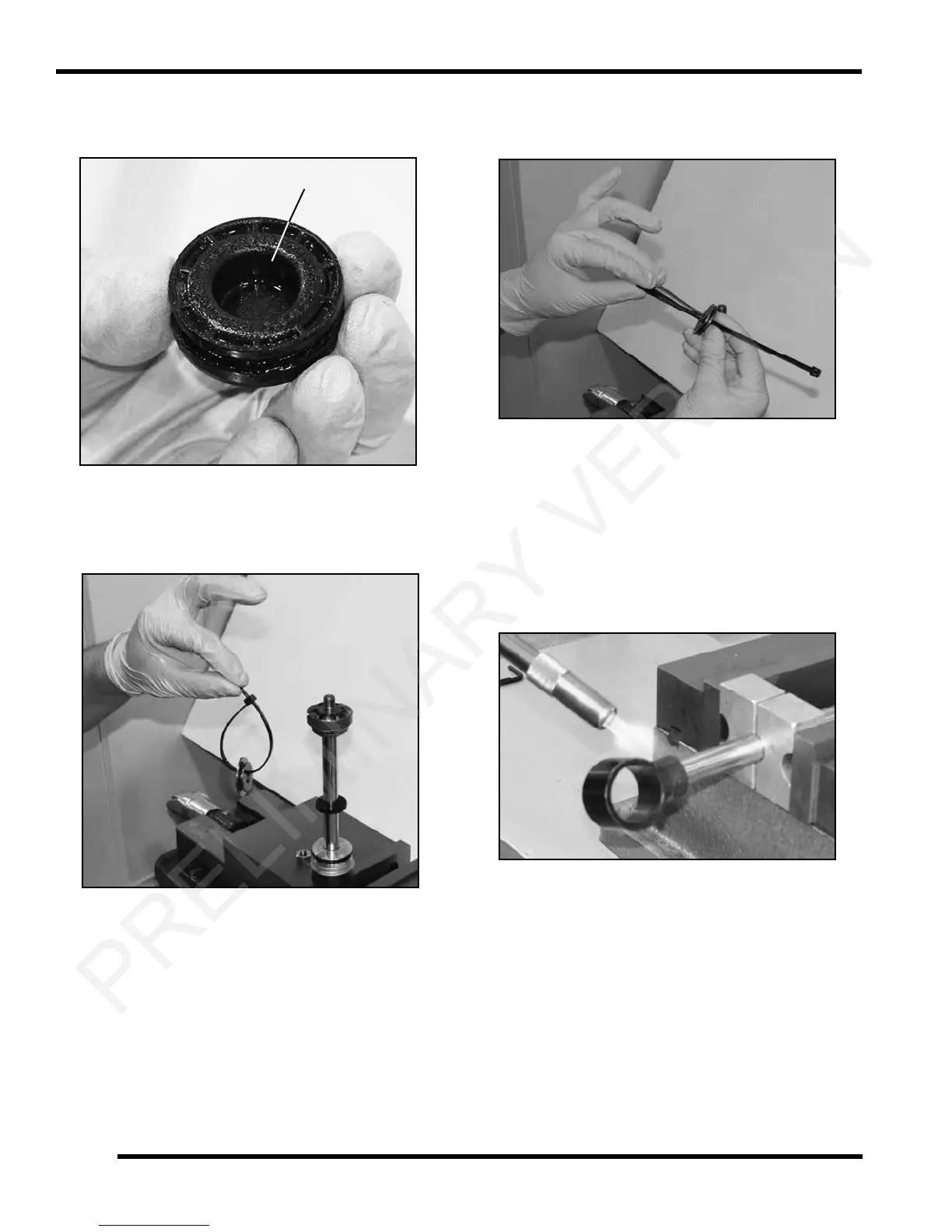
25. If shock shaft eyelet service is required, mount the
sh
ock shaft in a bench vise using the shaft blocks.
26. Using a propane torch, heat the eyele
t to soften the
thread lock. Remove the eyelet from the shaft.
Remove residual thread lock using a wire brush and
small pick (Fig. 11).
 Loading...