362 Interpreting LED Codes
Interpreting LBX Terminator LEDs
The LBX terminator has two versions. Version 01 has four LEDs and Version 03 has six LEDs. For more
information, see LBX Board and Terminator
on page 345.
LBX Terminator Version 01 LEDs
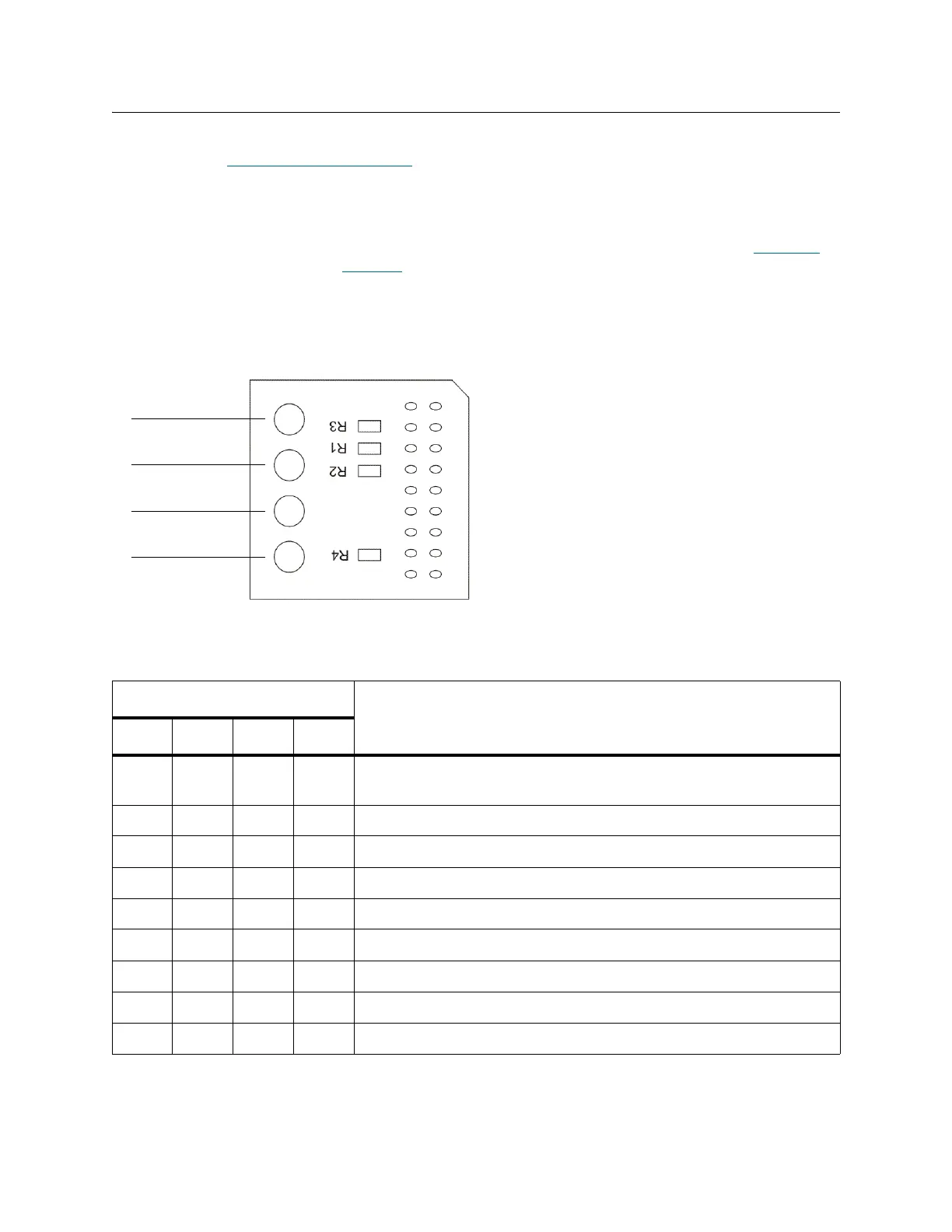
The LBX terminator has four green LEDs that indicate the presence of modules in the library. Figure 48
shows the locations of the LEDs. Table 27
describes how to interpret LED activity on the LBX terminator.
The terminator must be located in the LBX of the last expansion module. The LED status should reflect the
physical installed module count of the system.
Figure 48 Locations of LBX Terminator LEDs (Version 01)
Table 27 Explanations of LBX Terminator LED States (Version 01)
LED On/Off Combinations
Explanation
1234
Off Off Off Off Robotics are disabled, the access door is open, or the LBX
terminator is misaligned.
On Off Off Off The library has one control module and no expansion modules.
On On Off Off The library has one control module and one expansion module.
On On On Off The library has one control module and two expansion modules.
On On On On The library has one control module and three expansion modules.
On Off On On The library has one control module and four expansion modules.
On On Off On The library has one control module and five expansion modules.
On Off On Off The library has one control module and six expansion modules.
On Off Off On The library has one control module and seven expansion modules.

 Loading...