Scalar i6000 Installation Guide 47
3 Push the loose middle X-axis rail in the expansion module towards the X-axis rail in the control module
or expansion module to verify that there is no gap in the junction between the two rails.
4 While holding the X-axis rail against the adjoining rail use an 8 mm nut driver or open end wrench to
tighten the five 8 mm nuts on the X-axis rail alignment tool. This will align the two separate rails.
5 Working from left to right, tighten the ten 3 mm screws on the middle X-axis rail.
6 Use an 8 mm nut driver or open end wrench to loosen the five 8 mm nuts on the X-axis rail alignment
tool. Remove the tool from the X-axis rail.
7 Manually move the accessor over the rail junction points to verify that you cannot feel the junction.
Verifying the Middle X-Axis Rail Alignment
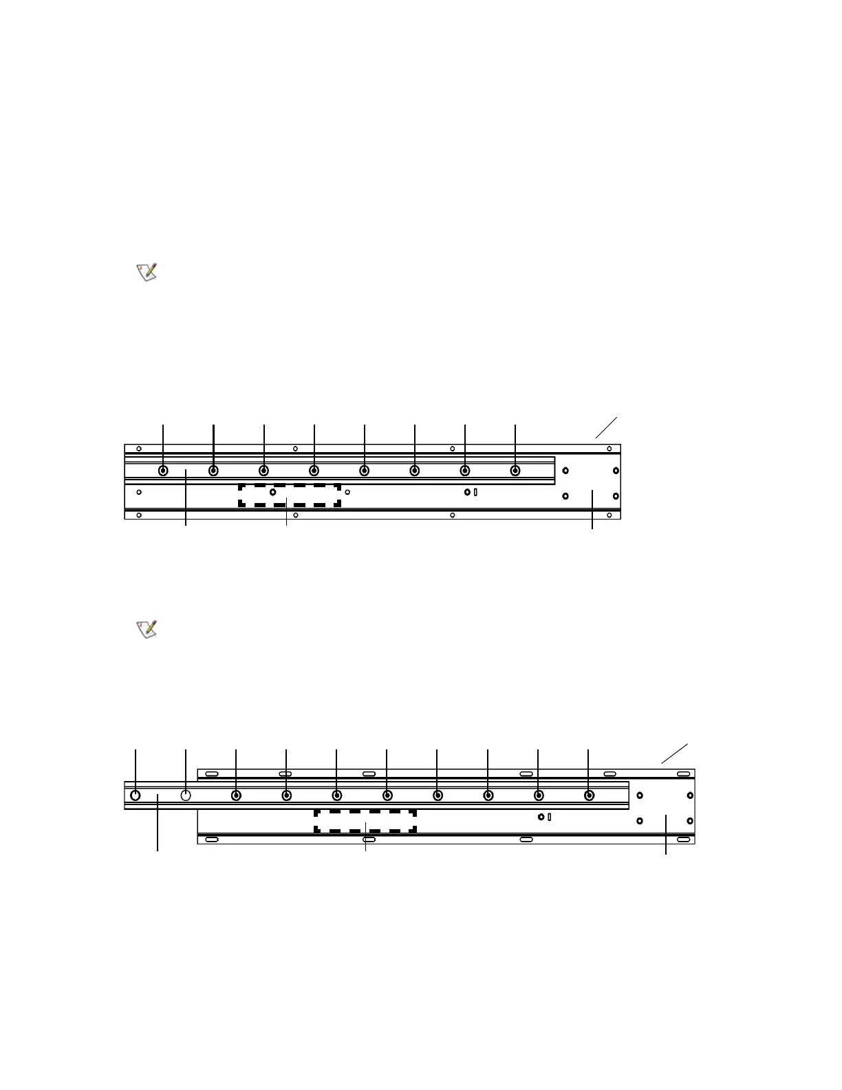
1 Place the digital level on the lower side of the control module X-axis rail between screws 3 and 4 as
counted from the left. Record this value.
2 Place the level against the lower side of the expansion module X-axis rail between screws 5 and 6 as
counted from the left.
3 Verify that value for the expansion module middle X-axis rail is within +/- 0.05 degrees of the value
recorded for the control module. Make note of this value.
4 If the rail is not within this tolerance, align it as follows:
There may be a slight clunk sound as you pass over the junction, but you
should not feel the transition between the rails in the accessor.
Do not place the level on the control module X-axis rail alignment pins.
middle
X-axis
X-axis rail
channel
12345678
level
location
Control Module Rail
middle
X-axis
X-axis rail
channel
12345678910
level
location
Expansion Module Rail

 Loading...