364 Interpreting LED Codes
Interpreting Power Supply LEDs
Power supply problems are reported in tickets. To physically identify a power supply, note the power supply
number and module number in the ticket details. Modules can have up to two power supplies each. The top
supply is #1 and the bottom supply is #2.
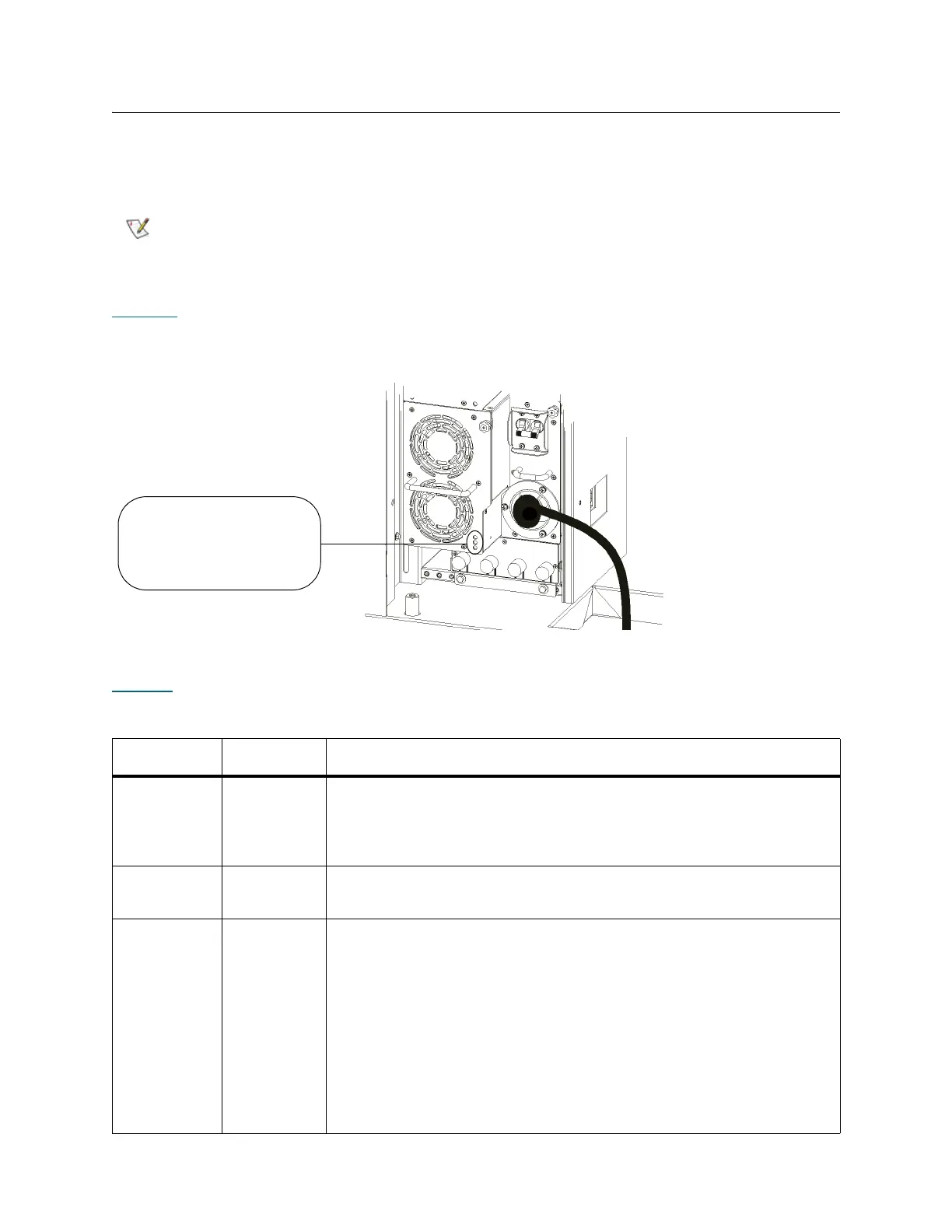
Figure 50
shows the locations and colors of the power supply LEDs.
Figure 50 Locations and Colors of Power Supply LEDs
Table 29
describes how to interpret LED activity that you might see.
The library can be physically configured to include up to eleven expansion
modules. The first seven expansion modules can contain power supplies if
drives are present.
Table 29 Explanations of Power Supply LED States
LED Color Represents Possible States and Explanations
Green
(top LED)
AC OK • Solid on — power supply’s AC input is above minimum requirements
to operate
• Solid off — power supply’s AC input is below minimum requirements
to operate
Green
(middle LED)
DC OK • Solid on — power supply’s output voltage is within specifications
• Solid off — power supply’s output voltage is outside of specifications
Blue (bottom
LED)
Fault • Solid on — indicates any of the following conditions:
•Power supply output is outside of specifications
•Current limit has been exceeded
•Temperature limit has been exceeded
•Fan failed while AC input is present and above minimum operating
voltage
•AC input is below minimum operating voltage
•PDU is on, but the Power button on the library’s indicator panel is off
• Solid off — no faults are detected
power supply LEDs
- top (AC OK) = green
- middle (DC OK) = green
- bottom (FAULT) = blue
 Loading...