RL78/F13, F14 CHAPTER 19 DTC
R01UH0368EJ0210 Rev.2.10 1426
Dec 10, 2015
CHAPTER 19 DTC
The DTC (data transfer controller) is a function that transfers data between memories without using the CPU. The DTC
is activated by a peripheral function interrupt to perform data transfers. The DTC and CPU use the same bus, and the DTC
takes priority over the CPU in using the bus.
To control DTC data transfers, control data comprised of a transfer source address, a transfer destination address, and
operating modes are allocated in the DTC control data area. Each time the DTC is activated, the DTC reads control data to
perform data transfers. The DTC control data area is allocated in the RAM space set by the DTCBAR register.
The high-speed transfer is realized by allocating the dedicated control data in the SFR area instead of the RAM area.
19.1 Overview
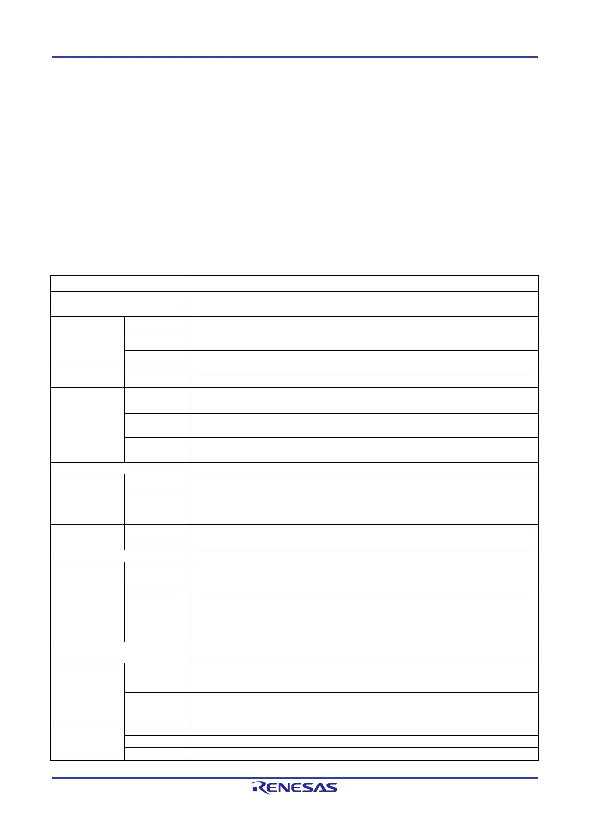
Table 19-1 lists the DTC specifications.
Table 19-1. DTC Specifications
Item Specification
Activation sources 44 sources max.
Allocatable control data 24 sets/2 sets (high-speed transfer)
Address space
which can be
transferred
Address space 64 Kbytes (F0000H to FFFFFH), excluding general-purpose registers
Sources
Note 2
1st SFR area, RAM area (excluding general-purpose registers), mirror area
Note 1
, data flash
memory area
Note 1
, 2nd SFR area
Destinations 1st SFR area, RAM area (excluding general-purpose registers), 2nd SFR area
Maximum number
of transfers
Normal mode 256 times
Repeat mode 255 times
Maximum size of
block to be
transferred
Normal mode
(8-bit transfer)
256 bytes/1 byte (high-speed transfer)
Normal mode
(16-bit transfer)
512 bytes/2 bytes (high-speed transfer)
Repeat mode 255 bytes/1 byte at 8-bit transfer (high-speed transfer)/2 bytes at 16-bit transfer (high-speed
transfer)
Unit of transfers 8 bits/16 bits
Transfer mode Normal mode
Transfers end on completion of the transfer causing the DTCCTj and HDTCCTm registers value
to change from 1 to 0.
Repeat mode
On completion of the transfer causing the values of the DTCCTj and HDTCCTm registers to
change from 1 to 0, the repeat area address is initialized and the DTRLDj register value is
reloaded to the DTCCTj and HDTCCTm registers to continue transfers.
Address control Normal mode Fixed or incremented
Repeat mode Addresses of the area not selected as the repeat area are fixed or incremented.
Priority of activation sources Refer to Table 19-5 DTC Activation Sources and DTC Vector Addresses.
Interrupt request Normal mode
When the data transfer causing the DTCCTj and HDTCCTm registers value to change from 1 to
0 is performed, the activation source interrupt request is generated for the CPU, and interrupt
handling is performed on completion of the data transfer.
Repeat mode
When the data transfer causing the values of the DTCCTj and HDTCCTm registers to change
from 1 to 0 is performed while the RPTINT and HRPTINTm bits in the DTCCRj and HDTCCRm
registers, respectively are 1 (interrupt generation enabled), the activation source interrupt
request is generated for the CPU, and interrupt handling is performed on completion of the
transfer.
Transfer start
When bits DTCENi0 to DTCENi7 in the DTCENi registers are 1 (activation enabled), data
transfer is started each time the corresponding DTC activation sources are generated.
Transfer stop Normal mode
When bits DTCENi0 to DTCENi7 are set to 0 (activation disabled).
When the data transfer causing the DTCCTj and HDTCCTm registers value to change from 1
to 0 is completed.
Repeat mode
When bits DTCENi0 to DTCENi7 are set to 0 (activation disabled).
When the data transfer causing the values of the DTCCTj and HDTCCTm registers to change
from 1 to 0 is completed while the RPTINT bit is 1 (interrupt generation enabled).
Operation in
standby mode
HALT state DTC operates
SNOOZE state DTC operates
STOP state DTC stops
 Loading...


