RL78/F13, F14 CHAPTER 6 TIMER ARRAY UNIT
R01UH0368EJ0210 Rev.2.10 480
Dec 10, 2015
6.6.2 TOmn Pin Output Setting
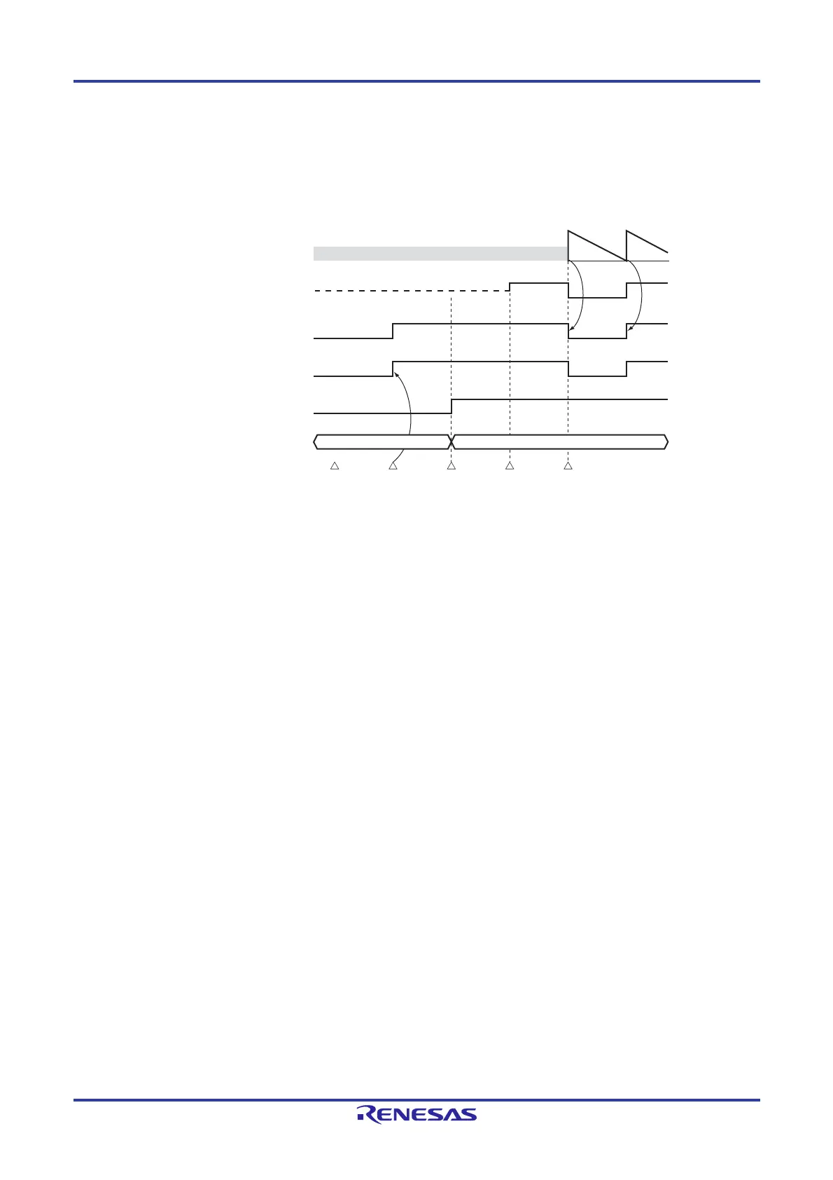
The following figure shows the procedure and status transition of the TOmn output pin from initial setting to timer operation
start.
Figure 6-35. Status Transition from Timer Output Setting to Operation Start
<1> The operation mode of timer output is set.
TOMmn bit (0: Master channel output mode, 1: Slave channel output mode)
TOLmn bit (0: Non-inverted output, 1: Inverted output)
<2> The timer output signal is set to the initial status by setting timer output register m (TOm).
<3> The timer output operation is enabled by writing 1 to the TOEmn bit (writing to the TOm register is disabled).
<4> The port mode control registers (PMCxx) are used to set the use of port pins for digital I/O (see 4.3.6 Port mode
control registers 7, 9, 12 (PMC7, PMC9, PMC12)).
<5> The port I/O setting is set to output (see 6.3.16 Port mode registers 1, 3, 4, 7, 12 (PM1, PM3, PM4, PM7,
PM12)).
<6> The timer operation is enabled (TSmn = 1).
Remarks 1. m: Unit number (m = 0, 1), n: Channel number (n = 0 to 7)
2. Unit 1 is not provided in the Group A products.
Channels 7 to 4 of unit 1 are not provided in the Group B, C, and D products.
TCRmn
Timer alternate-function pin
Timer output signal
TOEmn
TOmn
(Counter)
Undefined value (FFFFH after reset)
Write operation enabled period to TOmn
<1> Set TOMmn
Set TOLmn
<4> Set the port
to digital I/O
<5> Set the port
to output mode
<2> Set TOmn <3> Set TOEmn <6> Timer operation start
Write operation disabled period to TOmn
Hi-Z
 Loading...


