RL78/F13, F14 CHAPTER 8 TIMER RD
R01UH0368EJ0210 Rev.2.10 640
Dec 10, 2015
8.3.6 Complementary PWM Mode
In this mode, three normal-phases and three counter-phases of the PWM waveform are output with the same period
(three-phase, triangular wave modulation, and with dead time).
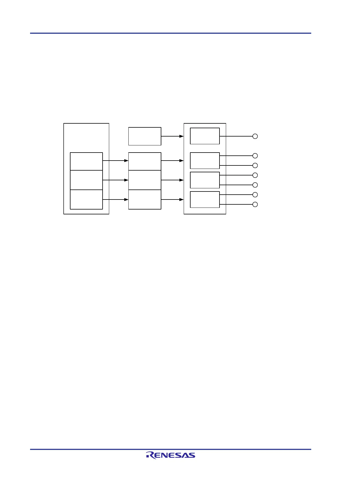
Figure 8-57 shows the Block Diagram of Complementary PWM Mode, Table 8-18 lists the Complementary PWM Mode
Specifications, and Figure 8-58 shows the Output Model of Complementary PWM Mode, and Figure 8-59 shows an
Operation Example in Complementary PWM Mode.
Figure 8-57. Block Diagram of Complementary PWM Mode
TRDIOC0
TRDIOB0
TRDIOD0
TRDIOA1
TRDIOC1
TRDIOB1
TRDIOD1
Buffer
TRDGRD0
register
TRDGRC1
register
TRDGRD1
register
TRDGRB0
register
TRDGRA0
register
TRDGRA1
register
TRDGRB1
register
PWM1
Normal-phase
Counter-phase
Normal-phase
Counter-phase
Normal-phase
Counter-phase
Period
Waveform control
PWM2
PWM3
 Loading...


