RL78/F13, F14 CHAPTER 14 COMPARATOR (RL78/F14 Only)
R01UH0368EJ0210 Rev.2.10 790
Dec 10, 2015
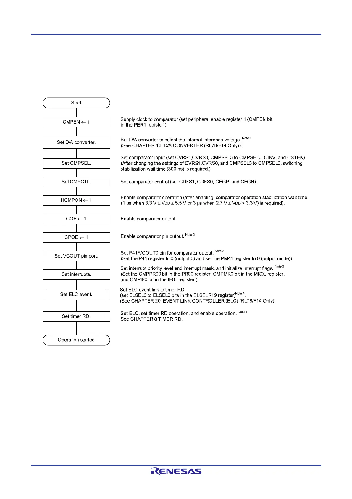
14.3.6 Comparator Setting Flowchart
Figure 14-13 shows the flowchart for setting the comparator-related registers.
Figure 14-13. Comparator Operation Setting Flowchart (when Using the timer RD Operation Triggered by Internal
Reference Voltage (D/A Converter Output), INTCMP0 Interrupt, or ELC Event)
Notes 1. This is not required when the external reference voltage is used.
2. This is not required when the comparator output is not output to the external pin.
3. Set the registers assigned to interrupt control.
4. This is not required when the ELC event is not used.
5. This is not required when the timer RD by the ELC event is not used.
 Loading...


