RL78/F13, F14 CHAPTER 26 VOLTAGE DETECTOR
R01UH0368EJ0210 Rev.2.10 1562
Dec 10, 2015
26.2 Configuration of Voltage Detector
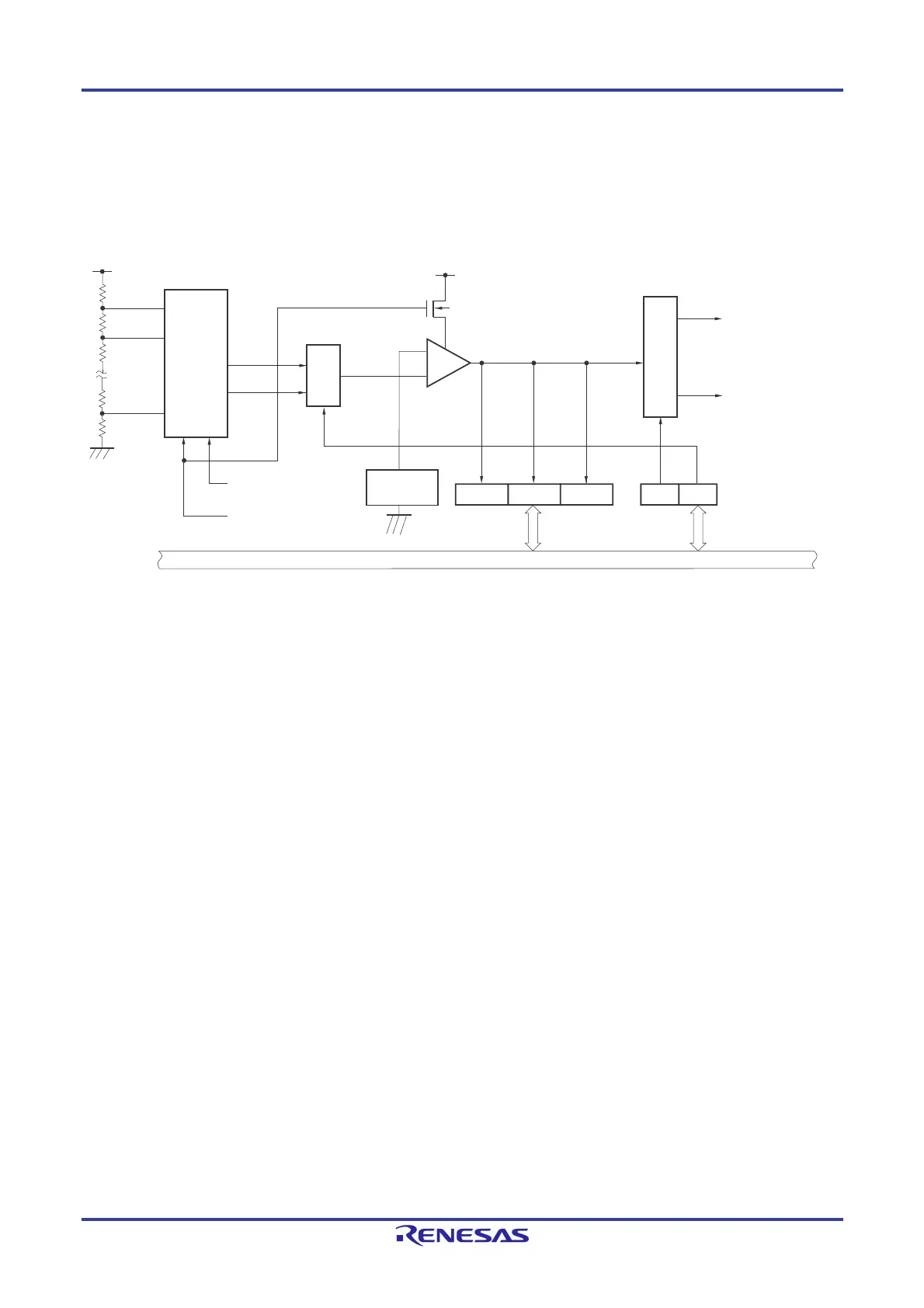
The block diagram of the voltage detector is shown in Figure 26-1.
Figure 26-1. Block Diagram of Voltage Detector
26.3 Registers Controlling Voltage Detector
The voltage detector is controlled by the following registers.
Voltage detection register (LVIM)
Voltage detection level register (LVIS)
Voltage detection
level register (LVIS)
Voltage detection
register (LVIM)
Internal reset signal
Option byte (000C1H)
VPOC2 to VPOC0
Option byte (000C1H)
LVIS1, LVIS0
LVIOMSKLVISEN
LVIF
INTLVI
V
DD
V
LVDH
V
LVDL
V
DD
N-ch
LVILV
LVIMD
Internal bus
Reference
voltage
source
Controller
Voltage detection
level selector
Selector
−
+
 Loading...


