RL78/F13, F14 CHAPTER 12 A/D CONVERTER
R01UH0368EJ0210 Rev.2.10 731
Dec 10, 2015
12.3.15 Port mode registers 3, 7 to 10, and 12 (PM3, PM7 to PM10, PM12)
When using the ANI0/P33 to ANI23/P105 and ANI24/P125 to ANI30/P74 pins for an analog input port, set the PMmn
bit to 1. The output latches of PMmn at this time may be 0 or 1.
If the PMmn bits are set to 0, they cannot be used as analog input port pins.
The PMm registers can be set by a 1-bit or 8-bit memory manipulation instruction.
Reset signal generation sets these registers to FFH.
Cautions 1. Available pins differ depending on the products. For details, see CHAPTER 2 PIN FUNCTIONS.
2. If a pin is set as an analog input port, not the pin level but 0 is always read.
Remark m = 3, 7 to 10, 12; n = 0 to 7
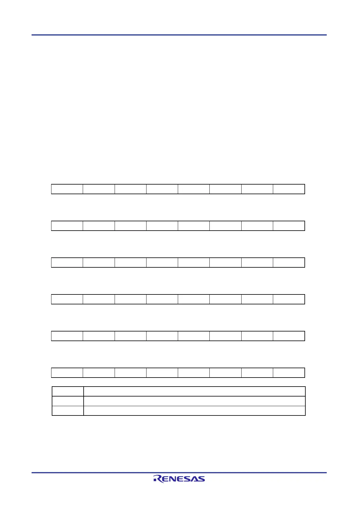
Figure 12-19. Formats of Port Mode Registers 3, 7 to 10, and 12 (PM3, PM7 to PM10, PM12)
(100-pin Products in the RL78/F14)
Address: FFF23H After reset: FFH R/W
Symbol 7 6 5 4 3 2 1 0
PM3 1 1 1 PM34 PM33 1 1 1
Address: FFF27H After reset: FFH R/W
Symbol 7 6 5 4 3 2 1 0
PM7 1 1 1 PM74 PM73 PM72 PM71 PM70
Address: FFF28H After reset: FFH R/W
Symbol 7 6 5 4 3 2 1 0
PM8 PM87 PM86 PM85 PM84 PM83 PM82 PM81 PM80
Address: FFF29H After reset: FFH R/W
Symbol 7 6 5 4 3 2 1 0
PM9 PM97 PM96 PM95 PM94 PM93 PM92 PM91 PM90
Address: FFF2AH After reset: FFH R/W
Symbol 7 6 5 4 3 2 1 0
PM10 1 1 PM105 PM104 PM103 PM102 PM101 PM100
Address: FFF2CH After reset: FFH R/W
Symbol 7 6 5 4 3 2 1 0
PM12 1 1 PM125 1 1 1 1 PM120
PM bit I/O mode selection
0 Output mode (output buffer on)
1 Input mode (output buffer off)
Caution When using AV
REFP and AVREFM, specify ANI0 and ANI1 as the analog input channels and specify
input mode by using the port mode register.
 Loading...


