RL78/F13, F14 CHAPTER 22 KEY INTERRUPT FUNCTION
R01UH0368EJ0210 Rev.2.10 1516
Dec 10, 2015
22.2 Configuration of Key Interrupt
Table 22-2 shows the configuration of the key interrupt. Figure 22-1 is the block diagram of the key interrupt.
Table 22-2. Configuration of Key Interrupt
Item Configuration
Control register Key return mode register (KRM)
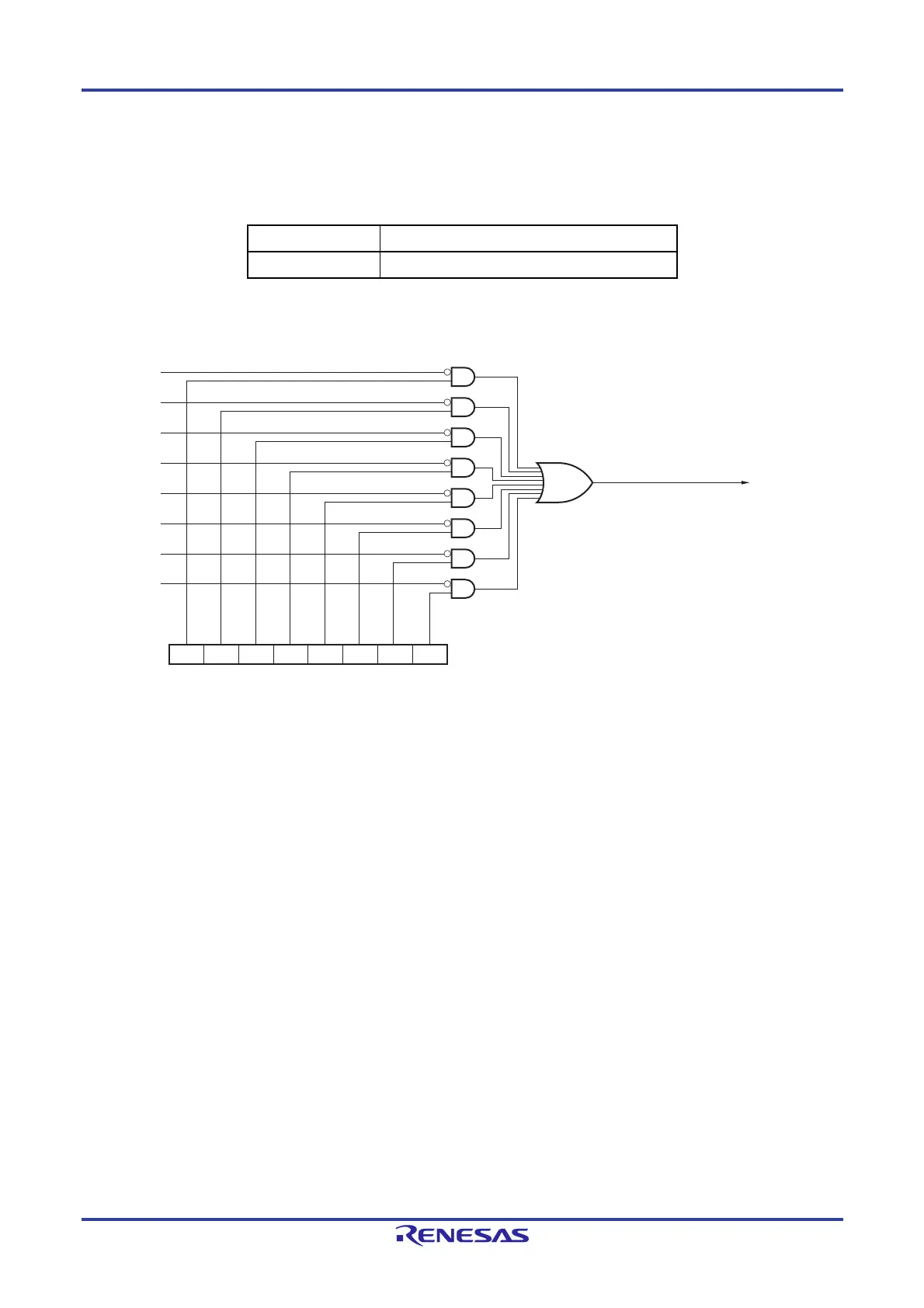
Figure 22-1. Block Diagram of Key Interrupt
INTKR
Key return mode register (KRM)
KRM7
KRM6
KRM5 KRM4 KRM3 KRM2 KRM1 KRM0
KR7
KR6
KR5
KR4
KR3
KR2
KR1
KR0
 Loading...


