RL78/F13, F14 CHAPTER 10 CLOCK OUTPUT/BUZZER OUTPUT CONTROLLER
R01UH0368EJ0210 Rev.2.10 691
Dec 10, 2015
10.3.3 Port mode register 14 (PM14)
These registers set input/output of port in 1-bit units.
When using the P140/PCLBUZ0 pins for clock output and buzzer output, clear PM140 bit and the output latch of
P140 to 0.
The PM14 register can be set by a 1-bit or 8-bit memory manipulation instruction.
Reset signal generation sets these registers to FFH.
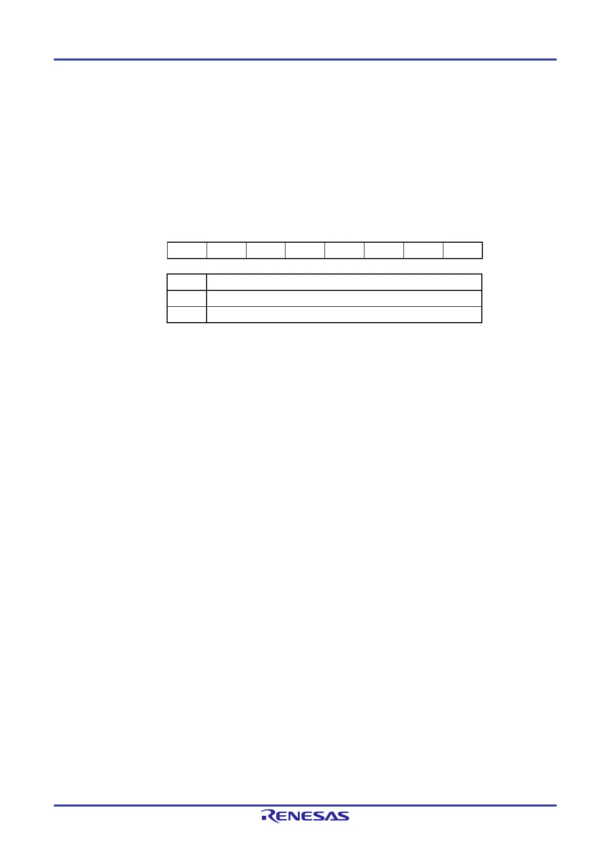
Figure 10-4. Format of Port Mode Register 14 (PM14)
Address: FFF2EH After reset: FFH R/W
Symbol 7 6 5 4 3 2 1 0
PM14 1 1 1 1 1 1 1 PM140
PMmn Pmn pin I/O mode selection (mn = 140)
0 Output mode (output buffer on)
1 Input mode (output buffer off)

 Loading...


