RL78/F13, F14 CHAPTER 27 SAFETY FUNCTIONS
R01UH0368EJ0210 Rev.2.10 1613
Dec 10, 2015
27.3.11 Digital output signal level detection function for I/O ports
By using the digital output signal level detection function for I/O ports, the digital output level of the pin can be read when
the port is set to output mode (the PMmn bit in the port mode register (PMm) is 0).
This function allows the output level of the pin to be read even when the PMnm (I/O mode) bit is set to output mode. As
a result, the CPU can determine the current output level is a high or low level. For details on the registers to control this
function, see CHAPTER 4 PORT FUNCTIONS.
<Control register>
(1) Port mode select register (PMS)
This register is used to select the output level from output latch level or pin output level when the port is output mode in
which PMm bit of port mode register (PMm) is 0.
This register can be set by a 1-bit or 8-bit memory manipulation instruction.
Reset signal generation clears these registers to 00H.
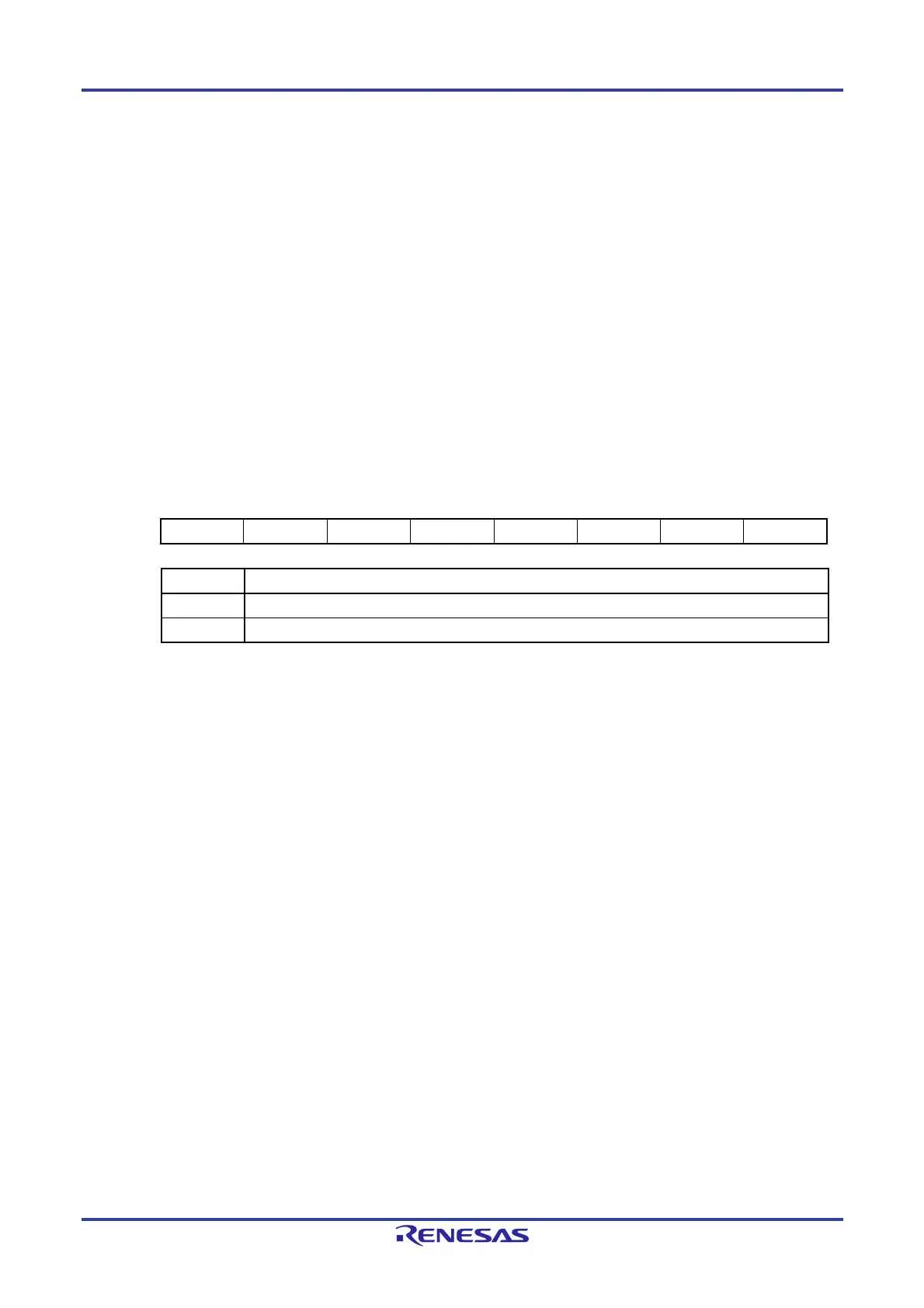
Figure 27-28. Format of Port Mode Select Register (PMS)
Address: F0077H After reset: 00H R/W
Symbol 7 6 5 4 3 2 1 0
PMS 0 0 0 0 0 0 0 PMS0
PMS0 Method for selecting output level to be read when port is output mode (PMmn = 0)
0 Pmn register value is read.
1 Output level of the pin is read.
Remark m = 0, 1, 3 to 10, 12 to 15
n = 0 to 7
 Loading...


