RL78/F13, F14 CHAPTER 26 VOLTAGE DETECTOR
R01UH0368EJ0210 Rev.2.10 1576
Dec 10, 2015
When setting an interrupt and reset mode (LVIMDS1, LVIMDS0 = 1, 0), voltage detection stabilization wait time for
400
s or 5 clocks of fIL is necessary after LVD reset is released (LVIRF = 1). After waiting until voltage detection stabilizes,
(0) clear the LVIMD bit for initialization. While voltage detection stabilization wait time is being counted and when the LVIMD
bit is rewritten, set LVISEN to 1 to mask a reset or interrupt generation by LVD.
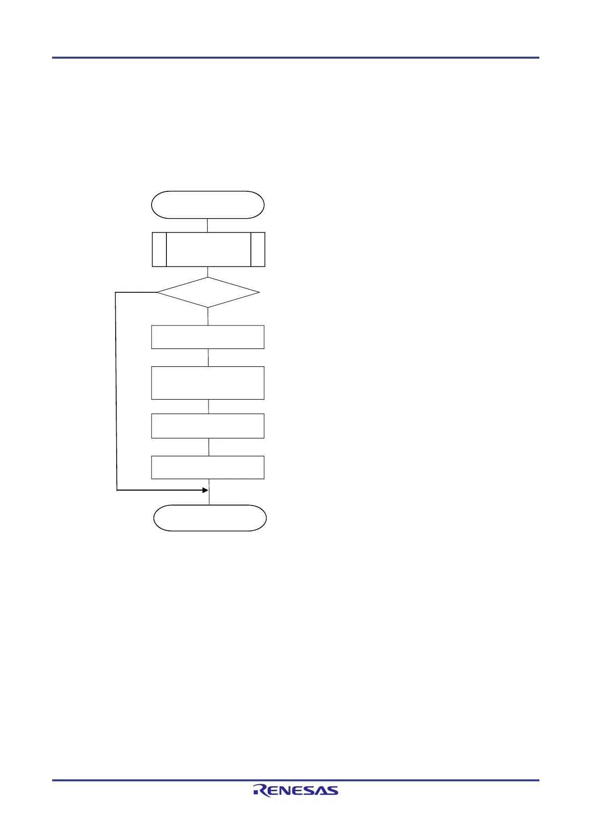
Figure 26-8 shows the procedure for initial setting of interrupt and reset mode.
Figure 26-8. Initial Setting of Interrupt and Reset Mode
Remark f
IL: Low-speed on-chip oscillator clock frequency
Set the LVIMD bit to 0 to set interrupt mode.
Refer to Fi
ure 26-9 Checkin
Reset Source.
Power supply started
LVISEN = 1
Voltage detection
stabilization wait time
LVIMD = 0
Set the LVISEN bit to 1 to mask voltage detection
(LVIOMSK = 1)
LVISEN = 0
Normal operation
Set the LVISEN bit to 0 to enable voltage detection.
Reset source
determined
Count 400
s or 5 clocks of fIL by software.
Yes
No
LVIRF = 1 ?
Check internal reset generation by LVD circuit
 Loading...


