RL78/F13, F14 CHAPTER 4 PORT FUNCTIONS
R01UH0368EJ0210 Rev.2.10 296
Dec 10, 2015
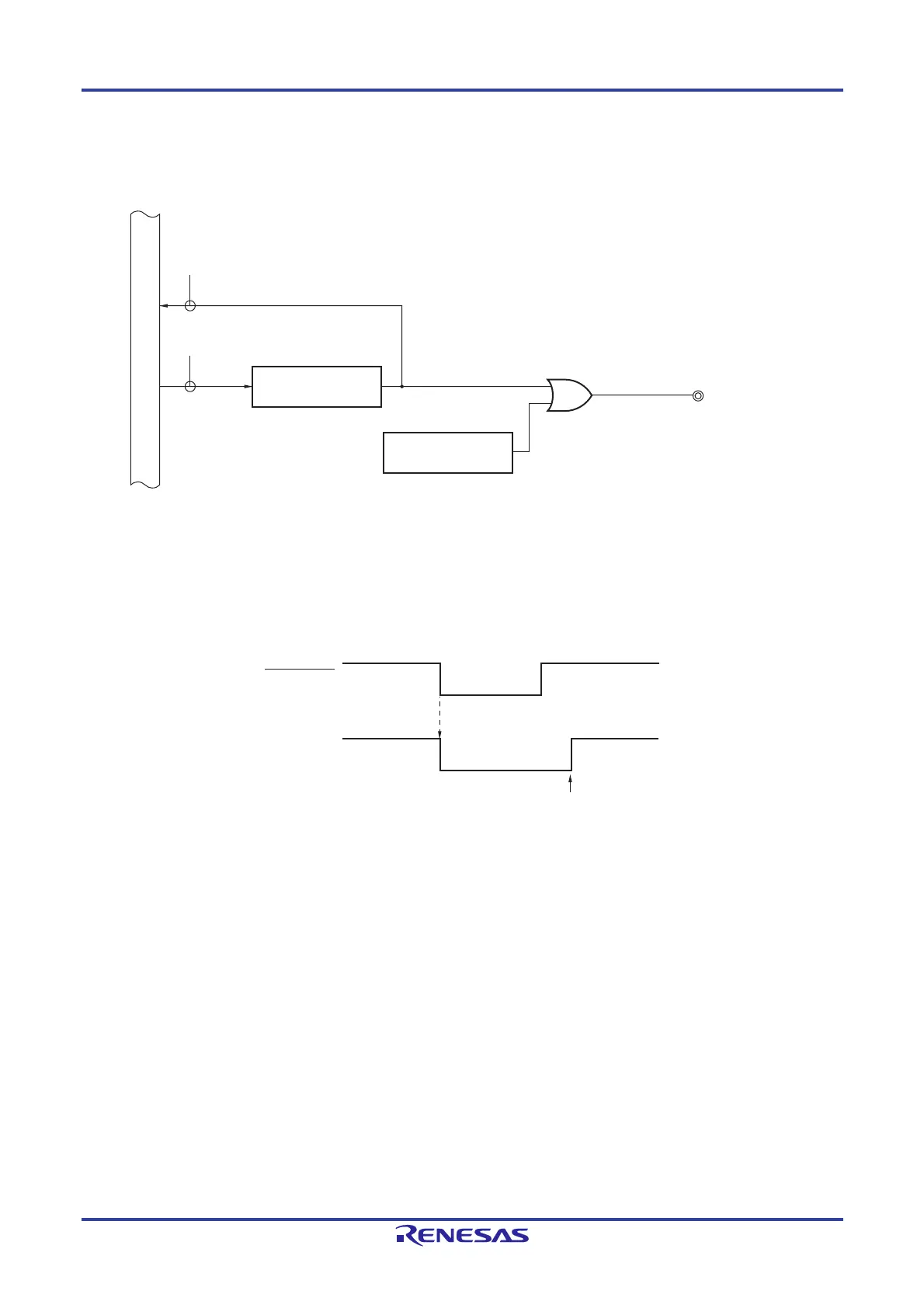
Figures 4-66 and 4-67 show block diagrams of port 13 for 100-pin products.
Figure 4-66. Block Diagram of P130
RD
P130
RESOUT
WR
PORT
P130/RESOUT
P13
Internal bus
Output latch
Alternate function
P13: Port register 13
RD: Read signal
WRxx: Write signal
Remark When reset is effected, P130 outputs a low level. If P130 is set to output a high level before reset is effected,
the output signal of P130 can be dummy-output as the CPU reset signal.
P130
Set by software
Reset signal
 Loading...


