RL78/F13, F14 CHAPTER 6 TIMER ARRAY UNIT
R01UH0368EJ0210 Rev.2.10 509
Dec 10, 2015
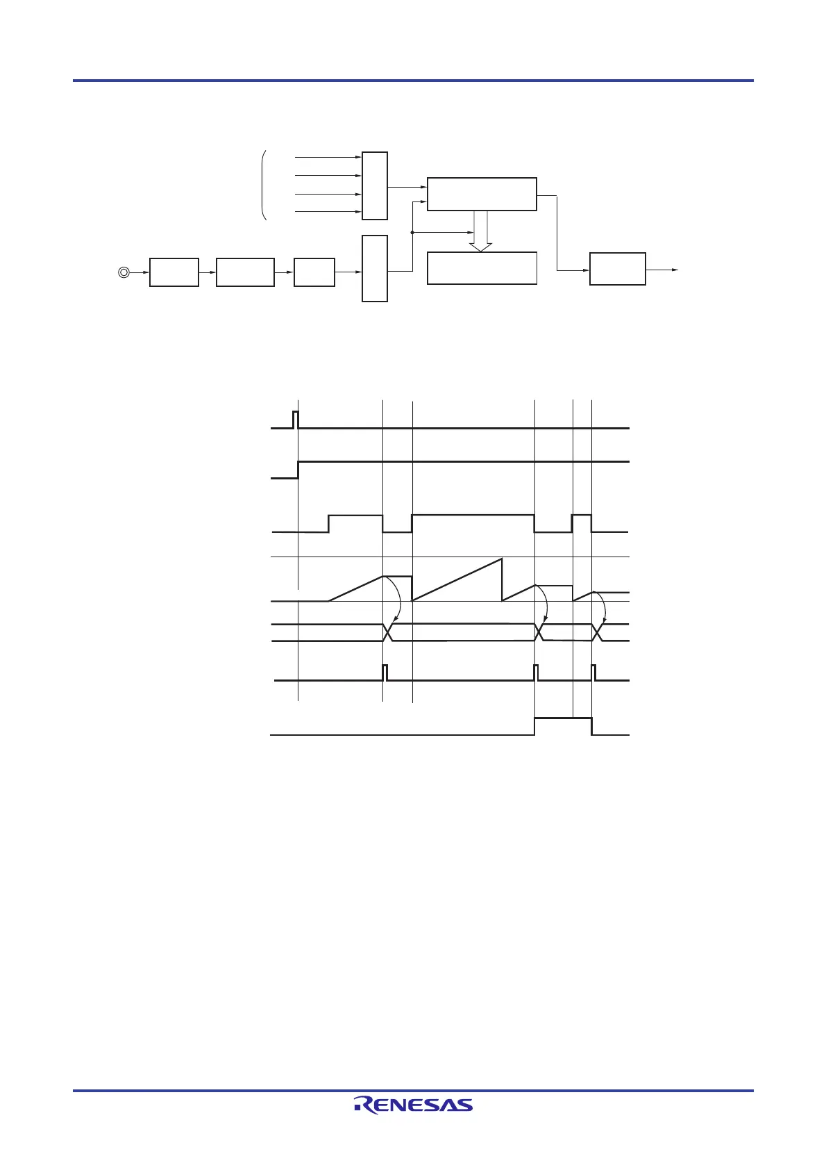
Figure 6-59. Block Diagram of Operation as Input Signal High-/Low-Level Width Measurement
Remark m: Unit number (m = 0, 1), n: Channel number (n = 0 to 7)
Figure 6-60. Example of Basic Timing of Operation as Input Signal High-/Low-Level Width Measurement
Remarks 1. m: Unit number (m = 0, 1), n: Channel number (n = 0 to 7)
2. TSmn: Bit n of timer channel start register m (TSm)
TEmn: Bit n of timer channel enable status register m (TEm)
TImn: TImn pin input signal
TCRmn: Timer count register mn (TCRmn)
TDRmn: Timer data register mn (TDRmn)
OVF: Bit 0 of timer status register mn (TSRmn)
3. Unit 1 is not provided in the Group A products.
Channels 7 to 4 of unit 1 are not provided in the Group B, C, and D products.
TImn pin
Noise
filter
Interrupt signal
(INTTMmn)
Interrupt
controller
Clock selection
Trigger selection
Timer counter
register mn (TCRmn)
Timer data
register mn (TDRmn)
Edge
detection
CKm2
CKm3
Operation clock
CKm0
CKm1
NFEN1 and
NFEN2
registers
TSmn
TEmn
TImn
TDRmn
TCRmn
b
0000H
a
c
INTTMmn
FFFFH
b
a
c
OVF
0000H
 Loading...


