RL78/F13, F14 CHAPTER 7 TIMER RJ
R01UH0368EJ0210 Rev.2.10 560
Dec 10, 2015
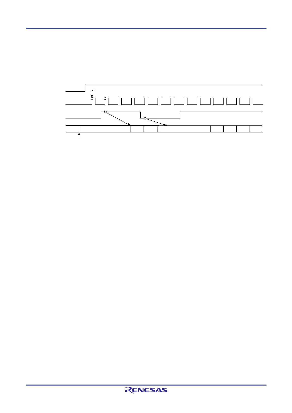
Figure 7-15. Operation Example 2 in Event Counter Mode
Event input starts
TSTART bit in
TRJCR0 register
Event input to
TRJIO0 pin
Timer RJ0 counter
INTP4 or
timer output signal
FFFFH FFFEH
FFFCH
The counter initial value is set
Timing example when the setting of operating mode is as follows:
TRJMR0 register: TMOD2, 1, 0 = 010B (event counter mode)
TRJIOC0 register: TIOGT1, 0 = 01B (event is counted during specified period for external interrupt pin)
TIPF1, 0 = 00B (no filter)
TEDGSEL = 0 (count at rising edge)
TRJISR0 register: RCCPSEL2 = 1 (high-level period is counted)
Note 2
Note 1
FFFDH
FFFBH
FFFAH
FFF9H
FFF8H
The following notes apply only when bits TIOGT1 and TIOGT0 in the TRJIOC0 register are 01B or 10B for the setting of operating mode in event count mode.
Notes 1. To control synchronization, there is a delay of two cycles of the count source until count operation is affected.
2. Count operation may be performed for two cycles of the count source immediately after the count is started, depending on the previous state before
the count is stopped.
To disable the count for two cycles immediately after the count is started, write 1 to the TSTOP bit in the TRJCR0 register to initialize the internal
circuit, and then make operation settings before starting count operation.
 Loading...


