RL78/F13, F14 CHAPTER 8 TIMER RD
R01UH0368EJ0210 Rev.2.10 627
Dec 10, 2015
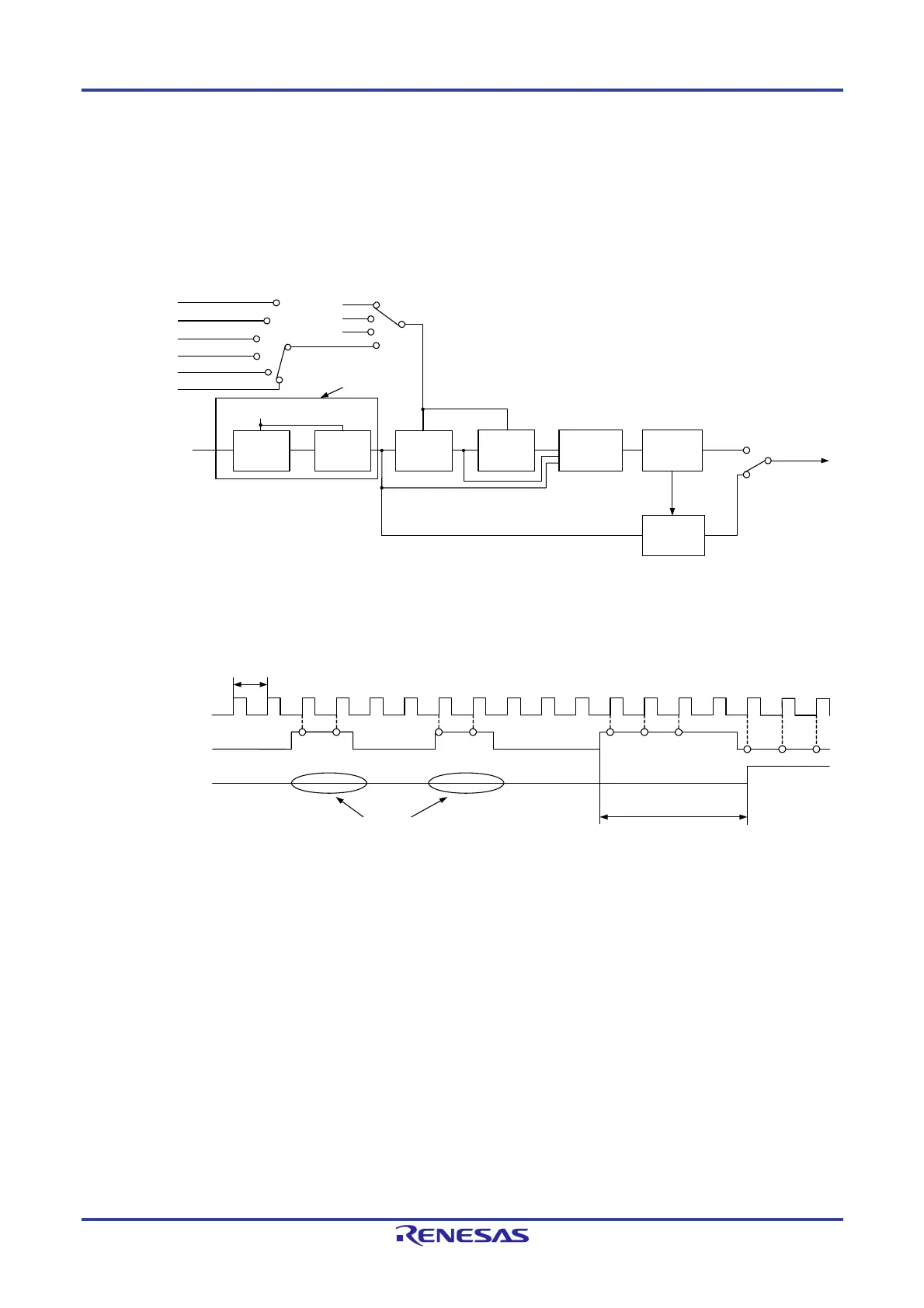
(2) Digital Filter
The TRDIOji input (i = 0 or 1, j = A, B, C, or D) is sampled, and when the sampled input level matches three times,
its level is determined. Select the digital filter function and sampling clock using the TRDDFi register.
Figure 8-47 shows the Block Diagram of Digital Filter.
Figure 8-47. Block Diagram of Digital Filter
C
DQ
Latch
Match detection
circuit
(flip-flop output)
Edge detection
circuit
DFj
Sampling clock
IOA2 to IOA0
IOB2 to IOB0
IOC3 to IOC0
IOD3 to IOD0
TRDIOji input signal
Clock period selected by
bits TCK2 to TCK0 or bits
DFCK1 and DFCK0
Sampling clock
TRDIOji input signal
Input signal through
digital filtering
If fails to match three times, is assumed
to be noise and not transmitted
Signal transmission delayed
up to five sampling clocks
Matched three times,
so recognized as
a signal change
Remark
i = 0 or 1, j = A, B, C, or D
TCK0 to TCK2: Bits in TRDCRi register
DFCK0, DFCK1, DFj: Bits in TRDDF register
IOA0 to IOA2, IOB0 to IOB2: Bits in TRDIORAi register
IOC0 to IOC3, IOD0 to IOD3: Bits in TRDIORCi register
C
DQ
Latch
Timer RD operating clock
f
CLK
= 101B
= 100B
= 011B
= 010B
= 001B
f
CLK/4
f
CLK/2
f
CLK/8
f
CLK/32
TRDCLK
f
CLK, fIH, fPLL, fSUB, and fIL
Note
= 000B
1
0
DFCK1 and DFCK0
f
CLK/32
f
CLK/8
f
CLK
Count source
= 00B
= 01B
= 10B
= 11B
TCK2 to TCK0
C
DQ
Latch
Synchronized by two
flip-flops
Edge detection
circuit
C
DQ
Latch
Notes 1. As the timer RD operating clock (f
TRD), fCLK is selected when FRQSEL4 = 0 in the user option byte
(000C2H/020C2H), (PLLDIV1 = 0 or SELPLLS = 0), and TRD_CKSEL = 0. f
IH is selected when FRQSEL4 =
1 and TRD_CKSEL = 0. f
PLL is selected when (PLLDIV1 = 1 and SELPLLS = 1) and TRD_CKSEL = 0. fSUB is
selected when SELLOSC = 0 and TRD_CKSEL = 1. f
IL is selected when SELLOSC = 1 and TRD_CKSEL =
1. For details, see Figure 8-40.
When selecting the count source for the timer RD, set the same clock source as the count source for f
CLK
before setting bit 4 (TRD0EN) in the peripheral enable register 1 (PER1).
2. With this setting, select f
CLK as the timer RD operating clock (fTRD).
 Loading...


