RL78/F13, F14 CHAPTER 15 SERIAL ARRAY UNIT
R01UH0368EJ0210 Rev.2.10 897
Dec 10, 2015
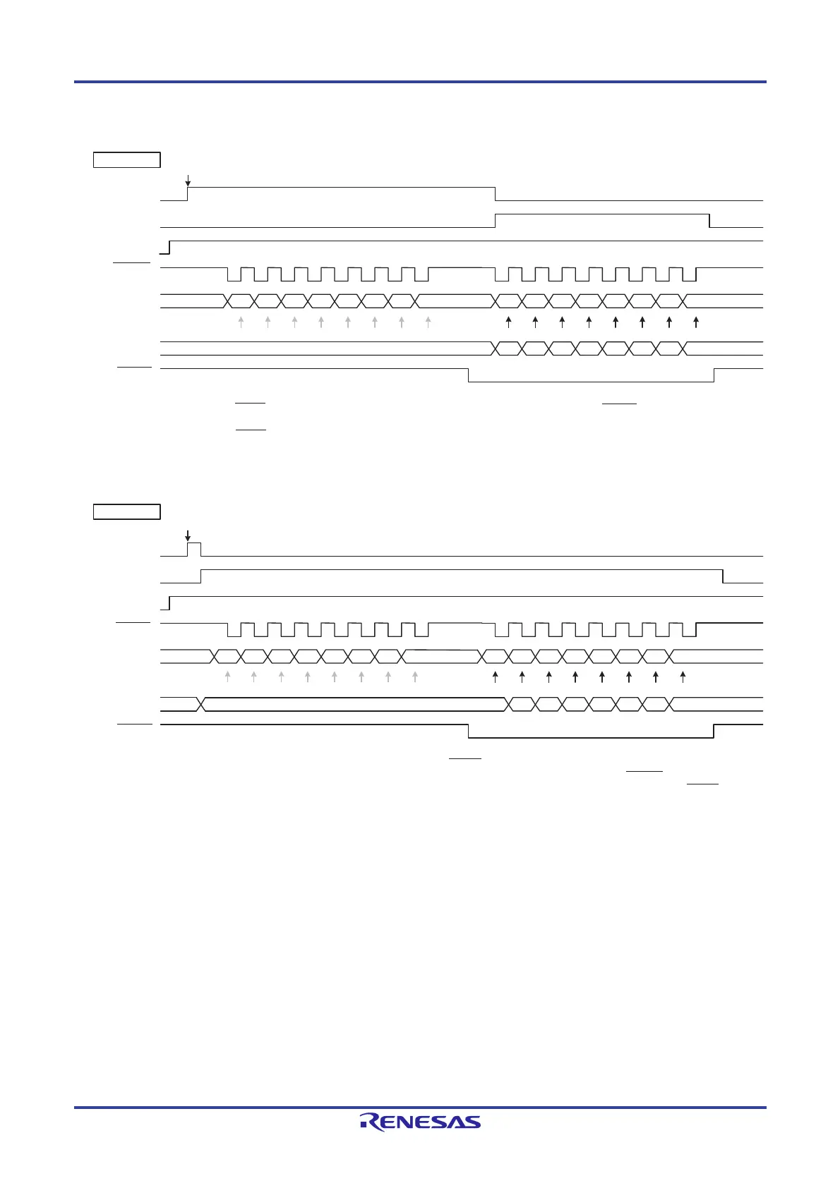
Figure 15-73. Slave Select Input Function Timing Diagram
Remark m: Unit number (m = 0, 1), n: Channel number (n = 0, 1)
TSFmn
SSEmn
SCKmn
(CKPmn = 0)
SImn
Sampling timing
SOnm
SSImn
DAPmn = 0
Transmit data is set
BFFmn
TSFmn
SSEmn
SCKmn
(CKPmn = 0)
SImn
Sampling timing
SOmn
SSImn
DAPmn = 1
Transmit data is set
bit7 bit6 bit5 bit4 bit3 bit2 bit1 bit0
bit7 bit6 bit5 bit4 bit3 bit2 bit1
bi
t0
BFFmn
If DAPmn = 1, when transmit data is set while SSImn is at high level, the first data (bit 7) is output to the
data output. However, no shift operation is performed even if the rising edge of SCKmn (serial clock)
arrives, and neither is receive data sampled in synchronization with the falling edge. When SSImn goes
to low level, data is output (shifted) in synchronization with the next rising edge and a reception operation
is performed in synchronization with the falling edge.
While SSImn is at high level, transmission is not performed even if the falling edge of SCKmn (serial clock) arrives,
and neither is receive data sampled in synchronization with the rising edge.
When SSImn goes to low level, data is output (shifted) in synchronization with the falling edge of the serial clock
and a reception operation is performed in synchronization with the rising edge.
bit7 bit6 bit5 bit4 bit3 bit2 bit1 bit0
bit7 bit6 bit5 bit4 bit3 bit2 bit1 bit0x
 Loading...


