EasyManua.ls Logo

Roland EGX-350 User Manual

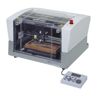
Roland EGX-350
124 pages
To Next Page IconTo Next Page
To Previous Page IconTo Previous Page
Page #13 background imageLoading...
Page #13 background image
Pour utiliser en toute sécurité
La manipulation ou l'utilisation inadéquates de cet appareil peuvent causer des blessures
ou des dommages matériels. Les précautions à prendre pour prévenir les blessures ou les
dommages sont décrites ci-dessous.
Avis sur les avertissements
ATTENTION
Utilisé pour avertir l'utilisateur d'un risque de décès ou de blessure grave en cas de
mauvaise utilisation de l'appareil.
PRUDENCE
Utilisé pour avertir l'utilisateur d'un risque de blessure ou de dommage matériel en cas
de mauvaise utilisation de l'appareil.
* Par dommage matériel, il est entendu dommage ou tout autre eet indésirable sur la
maison, tous les meubles et même les animaux domestiques.
À propos des symboles
Le symbole attire l'attention de l'utilisateur sur les instructions importantes ou les avertissements.
Le sens précis du symbole est déterminé par le dessin à l'intérieur du triangle. Le symbole à gauche
signie "danger d'électrocution."
Le symbole avertit l'utilisateur de ce qu'il ne doit pas faire, ce qui est interdit. La chose spécique à
ne pas faire est indiquée par le dessin à l'intérieur du cercle. Le symbole à gauche signie que l'appareil
ne doit jamais être démonté.
Le symbole prévient l'utilisateur sur ce qu'il doit faire. La chose spécique à faire est indiquée par le
dessin à l'intérieur du cercle. Le symbole à gauche signie que le l électrique doit être débranché de la
prise.
11

Table of Contents

Question and Answer IconNeed help?

Do you have a question about the Roland EGX-350 and is the answer not in the manual?

Roland EGX-350 Specifications

General IconGeneral
Drive SystemStepper motor
InterfaceUSB
Engraving Area350 x 300 mm
Engraving Area (mm)300 x 210 mm
Software Resolution (mm)0.01 mm/step
Spindle Speed7, 000 rpm
Power SupplyAC 100 - 240 V, 50/60 Hz
Acoustic Noise65 dB (A) or less (when not cutting)
Operating Temperature5 - 40 °C
Operating Humidity35 to 80% (no condensation)
External Dimensions (mm)680 x 580 x 430

Summary

Chapter 1 Getting Started

1-1 Machine Highlights

Overview of the machine's key features and capabilities.

1-2 Part Names and Functions

Identifies and explains the different parts of the machine.

Chapter 2 Installation and Setup

2-1 Checking the Included Items

Verifies all components received with the machine are present.

2-2 Installation

Detailed instructions for setting up and installing the machine.

2-3 Cable Connections

Guides on connecting essential cables for machine operation.

2-4 Selecting the Language

Procedure for choosing the display language on the machine.

2-5 Before Starting Operations

Preparation steps before initial machine operation, including spindle run-in.

Chapter 3 Basic Operation

3-1 Types of Emergency Stops to Ensure Safety

Explains different emergency stop methods and their functions.

3-2 Starting and Quitting

Instructions on how to power on and shut down the machine.

3-3 Using the Handy Panel

Details the functions and operation of the machine's handy panel.

3-4 Moving the Cutter

Covers manual and automatic movement of the cutting tool.

3-5 Spindle Operation

Instructions for starting, stopping, and adjusting spindle speed.

3-6 Pausing and Stopping Cutting

Procedures for pausing, resuming, or stopping the cutting process.

Chapter 4 Engraving

4-1 Flow of Engraving Operations

Outlines the sequence of steps for performing engraving tasks.

4-2 Mounting a Workpiece

Guides on how to properly secure materials onto the workpiece table.

4-3 Selection of the Cutter (Usage Examples)

Recommendations for choosing the right cutter for different materials.

4-4 Cutter Installation Method 1 (With Nose Unit)

Step-by-step guide for installing cutters with a nose unit.

4-8 Setting the XY Origin Point

Procedure to define the starting point for engraving operations.

4-9 Performing Engraving

Final steps to commence and manage the engraving process.

Chapter 5 Feature reference

5-1 Attaching the Vacuum Adapter for Chip Cleaning

Instructions for connecting a vacuum adapter for waste removal.

5-2 The Position of the Lock Lever

Explains the function and positioning of the lock lever.

5-3 Surface Leveling of the Workpiece Table

How to adjust the workpiece table for optimal flatness.

5-4 Menu List

Overview of the machine's menu structure and navigation.

5-5 Description of Menu Items

Detailed explanations of various menu options and settings.

Chapter 6 Maintenance

6-1 Daily Care

Routine cleaning and maintenance tasks for daily upkeep.

6-2 Maintenance and Inspection

Procedures for periodic maintenance and inspection of machine parts.

Chapter 7 Troubleshooting

7-1 Troubleshooting (Engraving)

Solutions for common engraving-related issues and problems.

7-2 Troubleshooting (Operation)

Guidance for resolving operational failures and malfunctions.

7-3 Responding to a Message

Explains how to interpret and act on machine display messages.

7-4 Responding to an Error Message

Provides steps to address and resolve machine error messages.

Chapter 8 Appendix

8-1 Examples of Settings for Cutting Parameters

Suggested parameters for various workpiece materials and cutters.

8-3 Interface Specifications

Technical details for serial and expansion connectors.

8-4 Main Unit Specification

Technical specifications and dimensions of the main machine unit.

Related product manuals