Chapter 5 Feature reference
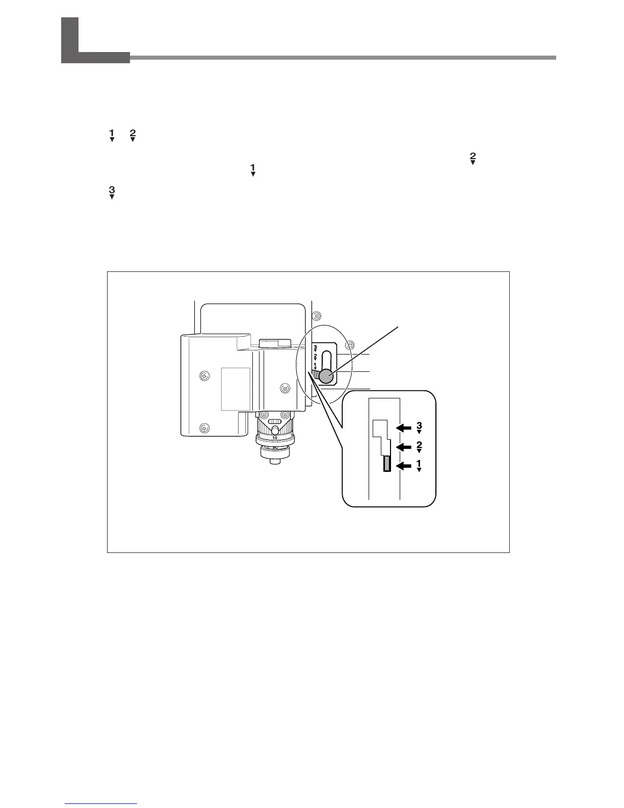
5-2 The Position of the Lock Lever
You change the position at which the lock lever is set to match the setting for automatic Z control.
P. 56 through 74, “Cutter Installation Method 1” through “Cutter Installation Method 4,” and p. 85, “Submenus”
Setting Position of the Lock Lever
or
When automatic Z control is set to “ON,” you set the lock lever at one of these positions. The spindle head is put into a
oating state, and the Z-axis origin point is determined by the height of the workpiece surface. The
setting applies
greater pressure to the workpiece than
.
When automatic Z control is set to “OFF,” you set the lock lever at this position. The spindle head is locked, and so the set-
ting for the Z-axis origin point must be made via the menu items. Setting the lock lever at this position when automatic
Z control is set to “ON” causes errors when making the origin-point settings or performing cutting, making the machine
perform an emergency stop.
P. 104, “Responding to an Error Message”
To raise : Simply lift up the lever.
To lower : Press the lever in slightly, then lower it.
Lock lever
 Loading...