EasyManuals Logo

Roland EGX-350 User Manual

Roland EGX-350
124 pages
To Next Page IconTo Next Page
To Previous Page IconTo Previous Page
Page #25 background imageLoading...
Page #25 background image
Chapter 1 Getting Started
23
1-2 Part Names and Functions
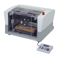
Front and Interior
* In this manual, the mechanisms around the spindle unit, including the spindle motor, are called the “spindle head.
Also, the rotary-axis area inside the spindle unit is called the “spindle.
Spindle head *
Lock lever
This locks or unlocks the spindle head.
P. 82, “The Position of the Lock Lever”
Spindle unit
Front cover
To ensure safety, opening this during
engraving or spindle rotation causes
an emergency stop to occur.
P. 39, “Emergency Stop Due to Opening or
Closing the Front Cover”
Emergency Stop button
Pressing this stops operation
of the machine.
P. 38, “Types of Emergency Stops
to Ensure Safety”
Workpiece table
The workpiece to be engraved
is mounted on this.
Handy panel
This is used to perform cutter movement and other
machine operations, and to make various settings.
P. 42, “Using the Handy Panel.

Table of Contents

Questions and Answers:

Question and Answer IconNeed help?

Do you have a question about the Roland EGX-350 and is the answer not in the manual?

Roland EGX-350 Specifications

General IconGeneral
Drive SystemStepper motor
InterfaceUSB
Engraving Area350 x 300 mm
Engraving Area (mm)300 x 210 mm
Software Resolution (mm)0.01 mm/step
Spindle Speed7, 000 rpm
Power SupplyAC 100 - 240 V, 50/60 Hz
Acoustic Noise65 dB (A) or less (when not cutting)
Operating Temperature5 - 40 °C
Operating Humidity35 to 80% (no condensation)
External Dimensions (mm)680 x 580 x 430

Related product manuals