 Loading...
Do you have a question about the Roland EGX-350 and is the answer not in the manual?
| Drive System | Stepper motor |
|---|---|
| Interface | USB |
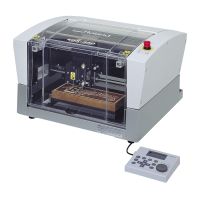
| Engraving Area | 350 x 300 mm |
| Engraving Area (mm) | 300 x 210 mm |
| Software Resolution (mm) | 0.01 mm/step |
| Spindle Speed | 7, 000 rpm |
| Power Supply | AC 100 - 240 V, 50/60 Hz |
| Acoustic Noise | 65 dB (A) or less (when not cutting) |
| Operating Temperature | 5 - 40 °C |
| Operating Humidity | 35 to 80% (no condensation) |
| External Dimensions (mm) | 680 x 580 x 430 |
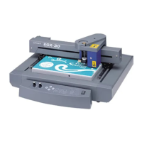
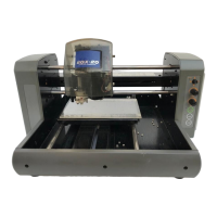
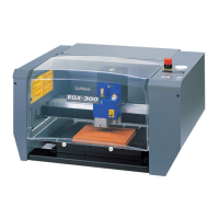
Overview of the machine's key features and capabilities.
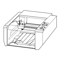
Identifies and explains the different parts of the machine.
Verifies all components received with the machine are present.
Detailed instructions for setting up and installing the machine.
Guides on connecting essential cables for machine operation.
Procedure for choosing the display language on the machine.
Preparation steps before initial machine operation, including spindle run-in.
Explains different emergency stop methods and their functions.
Instructions on how to power on and shut down the machine.
Details the functions and operation of the machine's handy panel.
Covers manual and automatic movement of the cutting tool.
Instructions for starting, stopping, and adjusting spindle speed.
Procedures for pausing, resuming, or stopping the cutting process.
Outlines the sequence of steps for performing engraving tasks.
Guides on how to properly secure materials onto the workpiece table.
Recommendations for choosing the right cutter for different materials.
Step-by-step guide for installing cutters with a nose unit.
Procedure to define the starting point for engraving operations.
Final steps to commence and manage the engraving process.
Instructions for connecting a vacuum adapter for waste removal.
Explains the function and positioning of the lock lever.
How to adjust the workpiece table for optimal flatness.
Overview of the machine's menu structure and navigation.
Detailed explanations of various menu options and settings.
Routine cleaning and maintenance tasks for daily upkeep.
Procedures for periodic maintenance and inspection of machine parts.
Solutions for common engraving-related issues and problems.
Guidance for resolving operational failures and malfunctions.
Explains how to interpret and act on machine display messages.
Provides steps to address and resolve machine error messages.
Suggested parameters for various workpiece materials and cutters.
Technical details for serial and expansion connectors.
Technical specifications and dimensions of the main machine unit.