Connection
7.1 Connecting the cooling
SIMOTICS M-1FE2 built-in motors
138 Hardware Installation Manual, 04/2020, A5E50074509B AA
7.1.3 Connecting the watercooling system
ay the cooling water supply intake and drain outlet connections according to project
Preconditions
● Ensure that the cooling water complies with the required cooling water specification. See
Chapter "Cooling (Page 63)".
● Ensure that cooling water with the required flow volume is available. See rating plate
(type plate).
Procedure
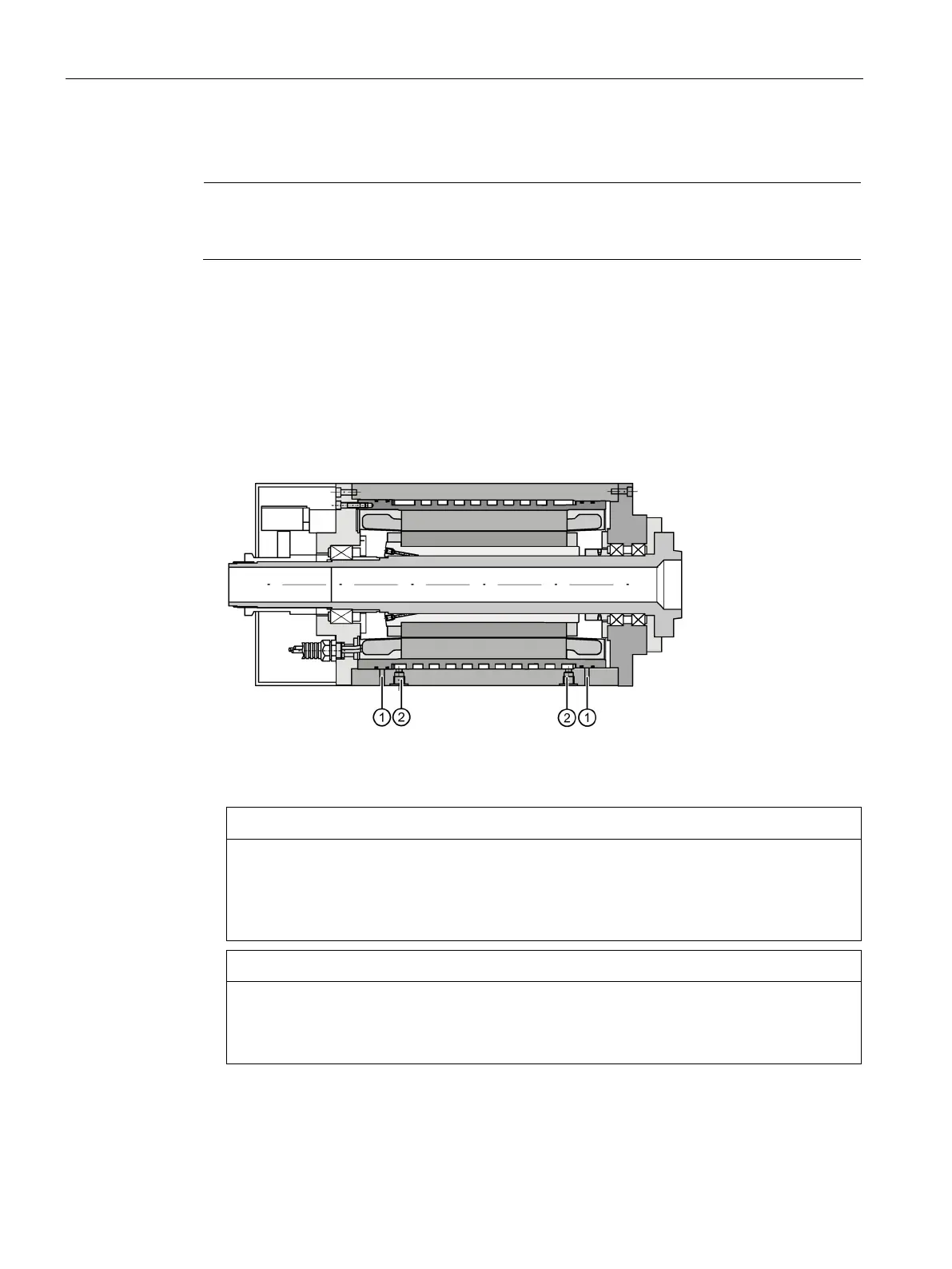
1. Connect the cooling water pipes for intake and drainage according to project
requirements.
Connections for the cooling water pipes
2. Set for the inlet a maximum permitted operating pressure of 0.7 MPa.
Risk of motor damage by voltage discharges resulting from condensation
If the stator winding is damp, its insulation resistance decreases. This can cause voltage
discharges that damage the windings.
• Keep the drain holes free so that condensation can escape freely.
Risk of motor damage by corrosion resulting from condensation
Condensation that does not escape can cause corrosion and motor damage.
• Keep the drain holes free so that condensation can escape freely.
3. Check that the drain holes are free so that condensation can escape freely.
4. Check the water cooling for leaks.
❒
 Loading...


