Description
3.3 Technical features and system requirements for built-in motors
SIMOTICS M-1FE2 built-in motors
Hardware Installation Manual, 04/2020, A5E50074509B AA
41
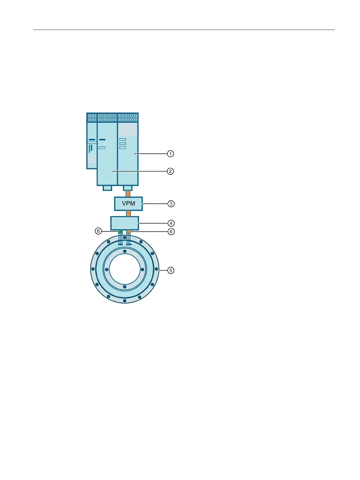
3.3.4.1 Operation on a power section
For operation of the 1FE218☐ on a power section, the two partial winding systems of the
stator are connected together in the motor terminal box using the following assignment. 1U1
and 2U1 → U, 2V1 and 2V1 → V, 1W1 and 2W1 → W
For this operational case, the values are specified on the datasheets or in the converter
software.
Voltage limiting module (VPM), if necessary
6 Motor cables of the partial windings (partial winding 1: 1U1, 1V1, 1W1; partial winding 2: 2U1,
Figure 3-6 General design 1FE218☐ on SINAMICS S120 booksize (one power section)
 Loading...


