Description
3.3 Technical features and system requirements for built-in motors
SIMOTICS M-1FE2 built-in motors
38 Hardware Installation Manual, 04/2020, A5E50074509B AA
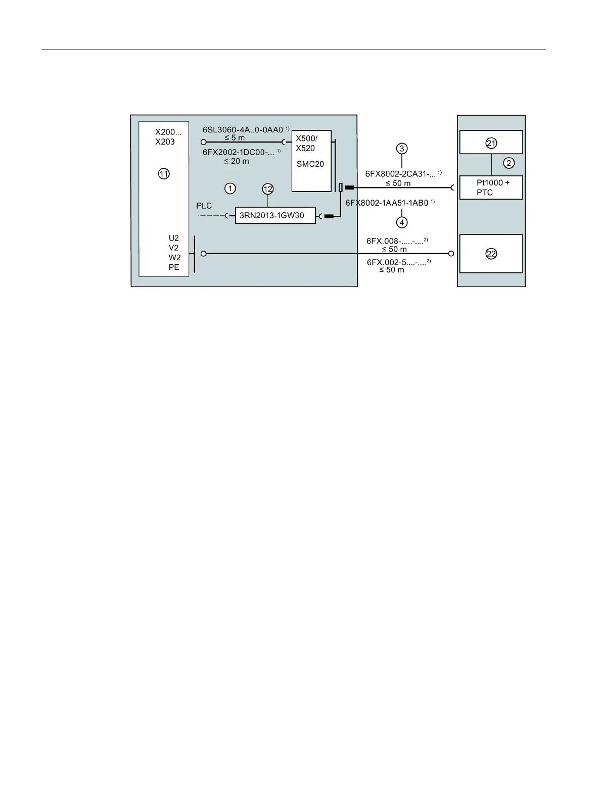
Motor with full protection, integrated into the system via SMC20
1)
Article numbers for prefabricated
MOTION-CONNECT signal cables, M23
connector size
2)
Article numbers for prefabricated
MOTION-CONNECT power cables
≲ 25 m in the case of star-delta changeover in
1 Control cabinet 21 Incremental encoder sin/cos 1 Vpp or EnDat
11 SINAMICS S120 Motor Modules, Booksize
format, DRIVE CLiQ communication via
22 1FE2 winding, connection via terminal box
12 Tripping unit 3 Signal cable for encoder and temperature
sensor,
17-pin M23 round connector
2 1FE2 built-in motor
4 Signal cable for PTC via tripping unit
3.3.4 Version and operating modes of the motor in the synchronous version
1FE2 motors of shaft height 180 (1FE218☐) consist of two winding systems, i.e. each motor
has six connecting cables (three connecting cables for each winding system).
Both partial windings are galvanically separated and only weakly coupled magnetically.
This means the motors can be operated in two different ways.
Option 1: Connection of the two windings to one (large) power section and the "classic"
operation of the motor on a CU/NCU.
 Loading...


