Description
3.3 Technical features and system requirements for built-in motors
SIMOTICS M-1FE2 built-in motors
42 Hardware Installation Manual, 04/2020, A5E50074509B AA
3.3.4.2 Operation on two power sections
Precondition
Two identical power sections (Motor Modules) with the same software release.
Both power sections are connected to the same DC link.
Note
The power of a 120 kW infeed (Active Line Modules) can be doubled by using an appropriate
parallel circuit Both power sections then operate on a shared DC link.
Otherwise deploy an infeed unit from the chassis area.
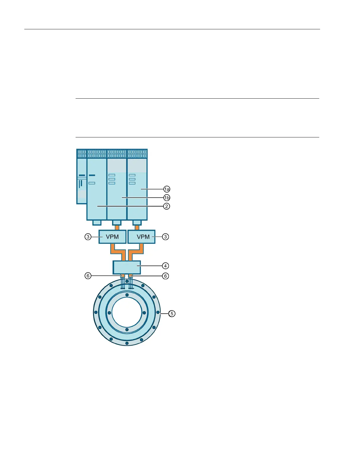
Master power unit (Motor Module)
Slave power unit (Motor Module)
Voltage limiting modules (VPM), if necessary
6 Motor cables of the partial windings (partial winding 1: 1U1, 1V1, 1W1; partial winding 2: 2U1,
Figure 3-7 General design 1FE2 booksize parallel circuit (two power sections)
 Loading...


