Connection
7.2 Electrical connection
SIMOTICS M-1FE2 built-in motors
Hardware Installation Manual, 04/2020, A5E50074509B AA
145
Guidelines for power connection
Also observe the following notes for providing the power connection:
● Lead the cable ends through the flexible tube or cable duct.
● Keep the inside of the terminal box clean and free from trimmed-off ends of wire.
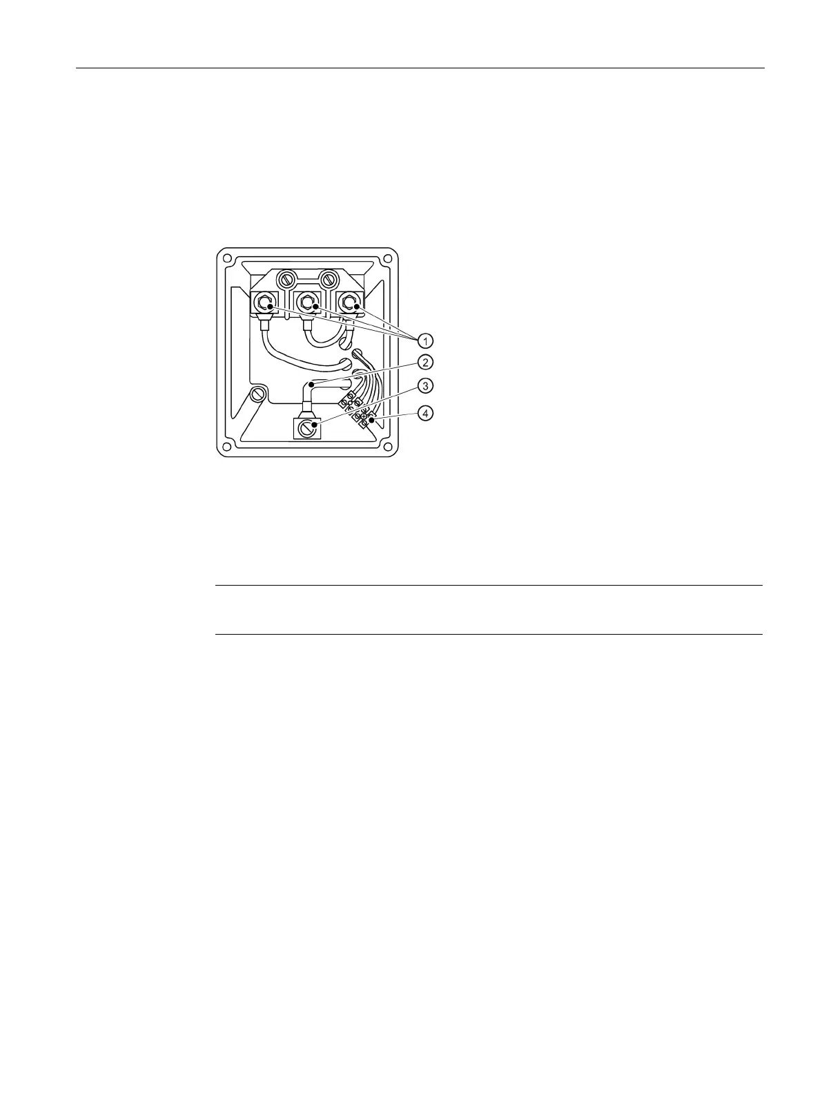
● See the following diagram for an example of terminal box design
Power connections (according to DIN 46200 can only be used in the motor spindle)
Internal protective conductor
Ground connection for internal and external protective conductors
Connectors for temperature sensors
Figure 7-2 Terminal boxes with permanent (internal) star connection (example)
Note
Connect the cables in accordance with project specifications of the
spindle manufacturer.
7.2.8 Information on cable routing
● Lay loose connection cables so that the insulation is not damaged.
● Make sure that the minimum bending radii are not exceeded. Minimum radius for fixed
installation: R = 4 x D
(D = outer cable diameter).
● Only remove insulation from the cable ends so that the insulation reaches up to the cable
lug, terminal, or wire end ferrule.
● Use cable lugs or wire end ferrules appropriate for the dimensions of the terminal board
connections and the cable cross-section. If necessary, install parallel connection cables.
● Ensure that the inside of the terminal box or connector is clean and free of cable cuttings
and moisture.
● Tighten all of the screws for the electrical connections (terminal board connections, with
the exception of the terminal strips) to the torque specified by the spindle manufacturer.
 Loading...


