Connection
7.2 Electrical connection
SIMOTICS M-1FE2 built-in motors
Hardware Installation Manual, 04/2020, A5E50074509B AA
143
Guidelines for power connection
Also observe the following notes for providing the power connection:
● Lead the cable ends through the flexible tube or cable duct.
● Keep the inside of the terminal box clean and free from trimmed-off ends of wire.
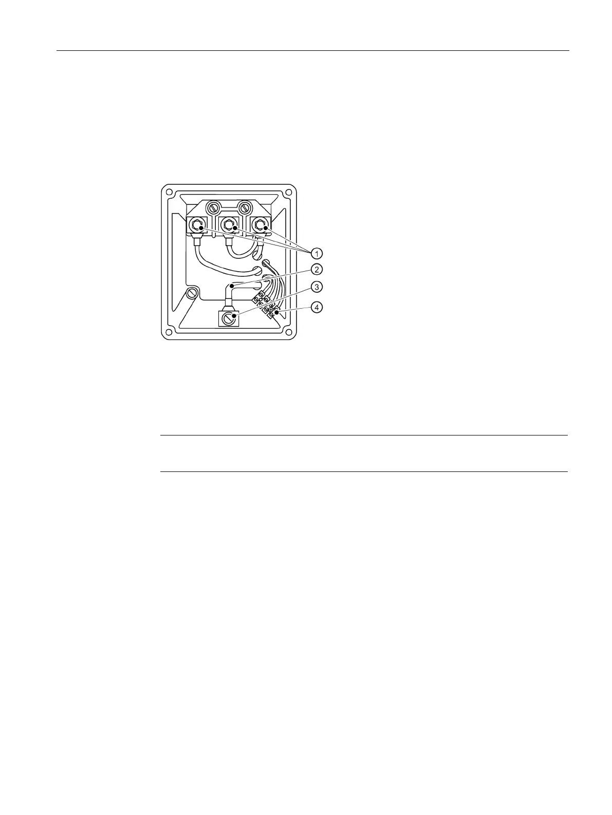
● See the following diagram for an example of terminal box design.
Power connections (according to DIN 46200 can only be used in the motor spindle)
Internal protective conductor
Ground connection for internal and external protective conductors
Connectors for temperature sensors
Figure 7-1 Terminal box (example)
Note
Connect the cables in accordance with project specifications of the spindle manufacturer.
 Loading...


