Connection
7.2 Electrical connection
SIMOTICS M-1FE2 built-in motors
Hardware Installation Manual, 04/2020, A5E50074509B AA
151
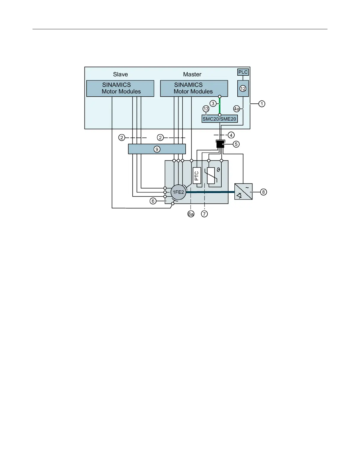
Connection overview for use of two power sections with the "SERVCOUP" OA software without VPM
Not available in this circuit
Tripping unit for evaluating the PTC triplet
SMC20/SME20, encoder on the motor side, connector kits 6FX2003-0SA12, 12-pin
DRIVE-CLiQ cable, trailable or conditionally trailable
Signal line, trailable or only conditionally trailable
Conductor in the signal cable from the PTC to the tripping unit
5 Signal connector, 17 pin, external thread, Article No.: 6FX2003-0SA17-....
Optional mounting flange for retrofitting, Article No.: 6FX2003-7DX00
Temperature sensor (+1 Pt1000 spare)
Figure 7-7 Connection overview with OA software without VPM
 Loading...


