Description
3.2 Overview of the motors
SIMOTICS M-1FE2 built-in motors
24 Hardware Installation Manual, 04/2020, A5E50074509B AA
Motor spindle design
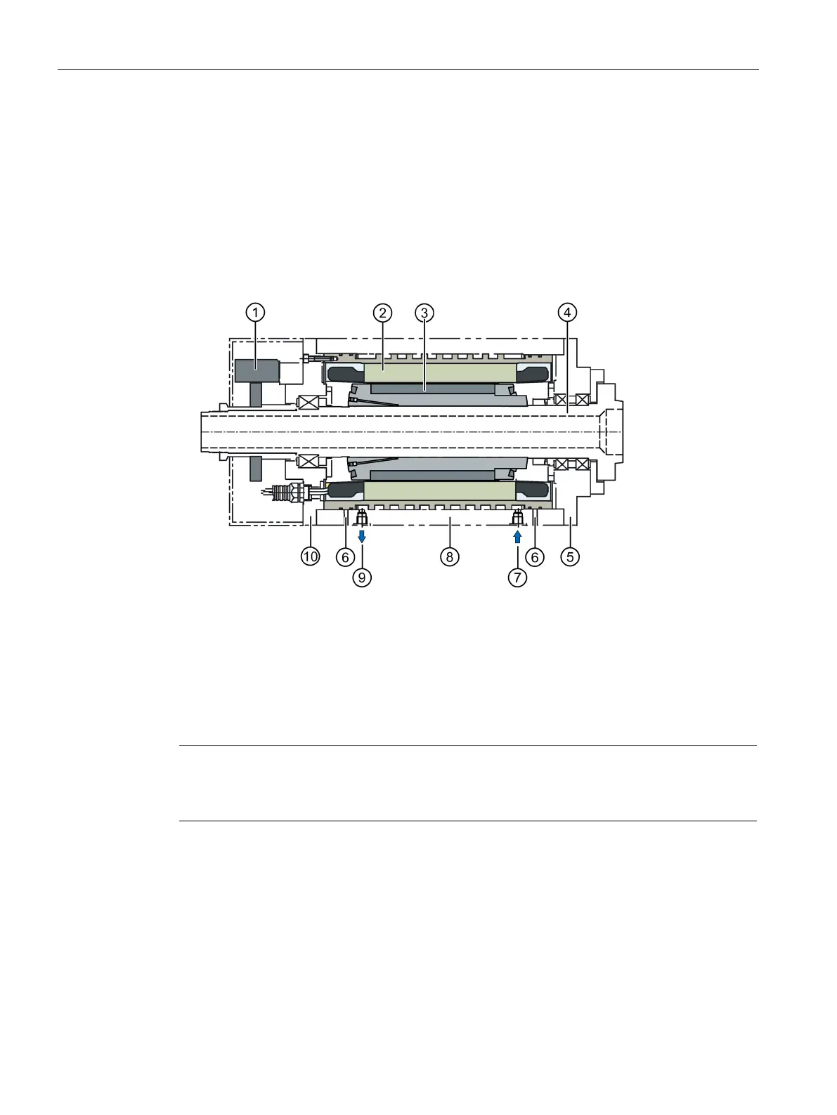
A motor spindle comprises the following modules (see the following diagram):
● Spindle housing
● Spindle shaft with bearings
● Built-in motor
● Cooling system
● Encoder system
Stator with cooling jacket
Inlet cooling water connection
Spindle shaft with bearings
Outlet cooling water connection
End shield DE (Drive End)
End shield NDE (Non Drive End)
Figure 3-1 Motor spindle design
Note
The spindle manufacturer is responsible for designing the bearings, lubrication and cooling.
A ferritic spindle shaft is a prerequisite in order to achieve the electrical parameters.
 Loading...


