Mechanical mounting
6.3 Installing/removing the rotor
SIMOTICS M-1FE2 built-in motors
Hardware Installation Manual, 04/2020, A5E50074509B AA
97
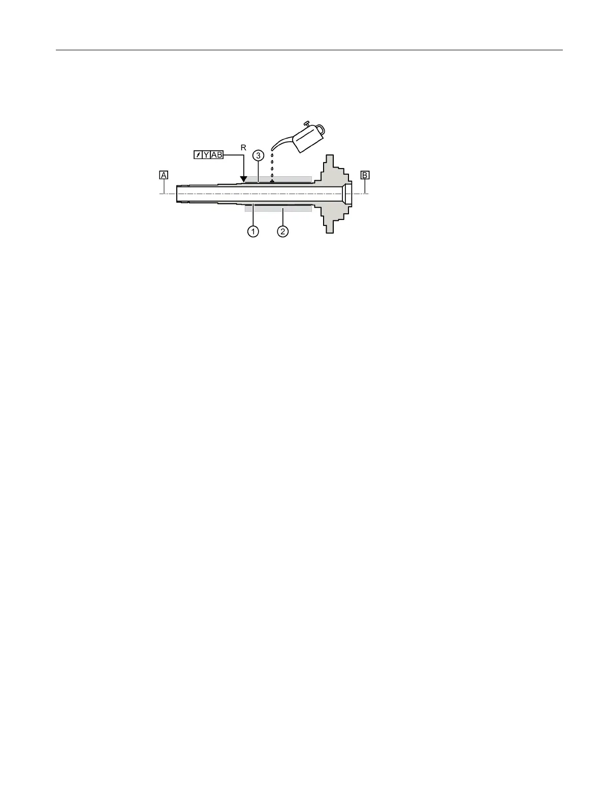
3. Measure and record the radial runout of the spindle to the reference plane (see
measurement plane "R")
Position of the rotor core
Oiled surface (assembly without stress relief)
Reference plane for radial runout check
Measured value (before and after assembly)
Spindle shaft axis (reference axis)
Figure 6-7 Checking the radial runout
4. If the stress of the rotor core is not relieved after assembly, rub mounting fluid, such as
SKF LHMF300, onto the joined surfaces
③.
❑
 Loading...


