3.1 Mounting and Connections
465
7SD5 Manual
C53000-G1176-C169-1
Interface
PROFIBUS
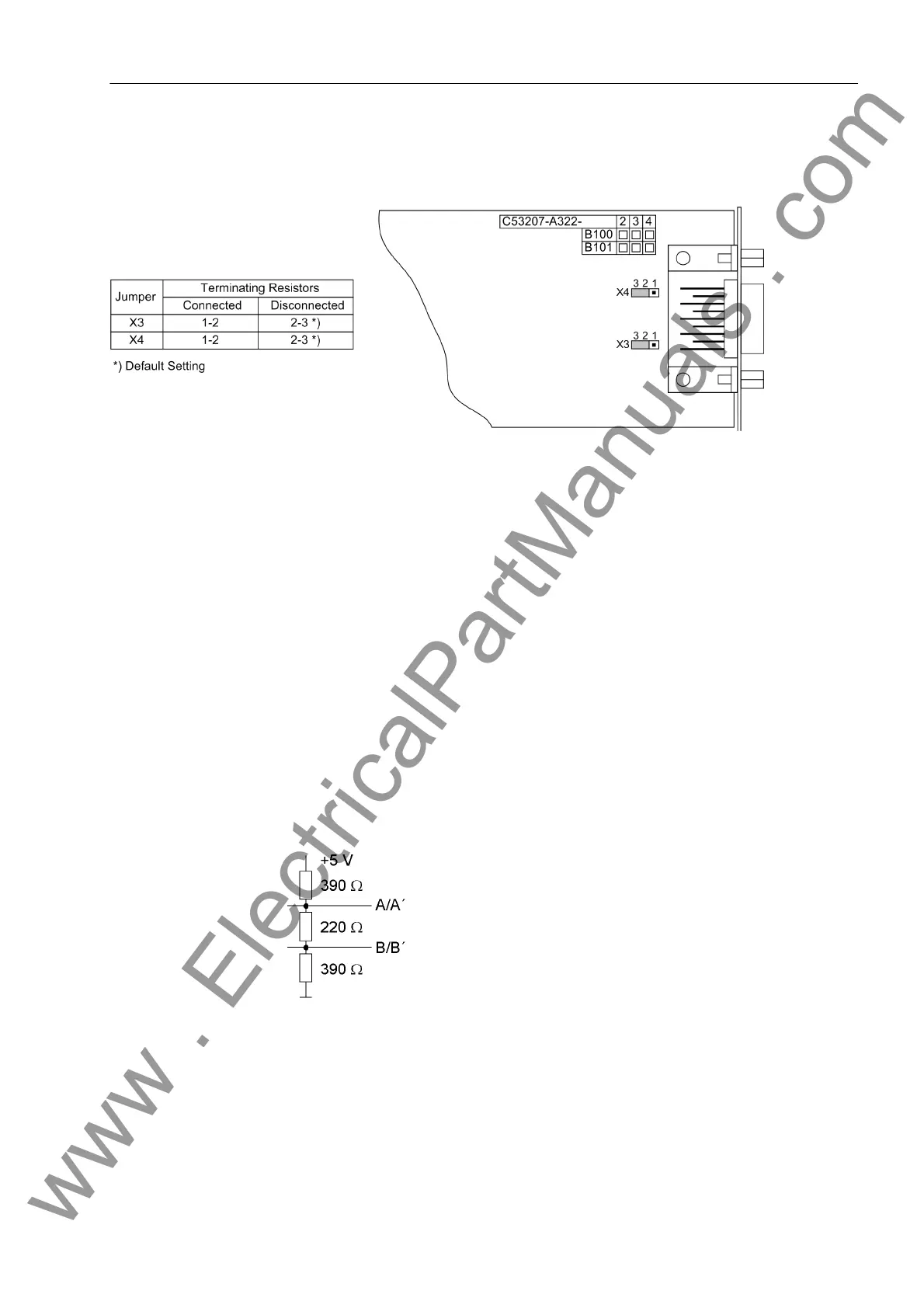
Figure 3-11 Location of the jumpers for configuring the PROFIBUS and DNP 3.0 interface terminating resistors
Te rm in a ti o n Busbar capable interfaces always require a termination at the last device to the bus,
i.e. terminating resistors must be connected. With the 7SD5 device, this concerns the
variants with RS485 or PROFIBUS interfaces.
The terminating resistors are on the RS485 or PROFIBUS interface module which is
located on the processor board C-CPU-1 (No. 1 in Figure 3-3 and 3-4).
Figure 3-8 shows the PCB of the C-CPU-1 with the layout of the modules.
The board with configuration as RS485 interface is shown in Figure 3-10, the module
for the PROFIBUS interface in Figure 3-11.
For the configuration of the terminating resistors both jumpers have to be plugged in
the same way.
On delivery the jumpers are set so that the terminating resistors are disconnected.
The terminating resistors can also be implemented outside the device (e.g. at the ter-
minal block), see Figure 3-12. In this case, the terminating resistors located on the
RS485 or PROFIBUS interface module must be switched off.
Figure 3-12 Termination of the RS485 interface (external)
www . ElectricalPartManuals . com
 Loading...


